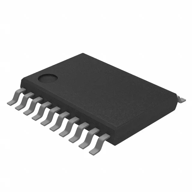
16 MHz CPU16 core with 1 KB flash — what fits in the firmware budget
The MSP430F2101IPWR runs the MSP430 CPU16 core at 16 MHz, a 16-bit RISC architecture with a single-cycle hardware multiplier. The 1 KB of on-chip flash (1 K × 8 plus 256 bytes of information memory) plus 128 bytes of RAM sets a tight firmware budget — the bootloader, interrupt vectors, and any runtime stack carve into that footprint before the application code starts. For a sensor node or simple control loop that fits in a few hundred instructions, this part works. If your BOM needs a UART stack or a non-trivial state machine, the flash fills fast — step through the linker map before committing.
Supply rails, temperature grade, and on-chip peripherals
On-chip peripherals include brown-out detection (BOR), power-on reset (POR), a PWM timer, and a watchdog timer (WDT). The slope A/D converter is a single-channel, successive-approximation type with no sample-and-hold — it works for slow-varying analog signals like temperature or battery voltage, but not for fast transients.
16 GPIOs in a 20-TSSOP — PCB layout and signal budget
All 16 are available for digital I/O, but the slope A/D input shares one pin with.0 — if you use the ADC, that pin is not available as a GPIO. The remaining 15 GPIOs are enough for a keypad matrix, LED indicators, and a few sensor inputs. Surface-mount only — no through-hole variant. Decouple with a 100 nF ceramic close to each Vcc pin; the supply range is wide enough that a single 10 µF bulk cap on the rail is sufficient for most layouts.
Active production, ROHS3, and compliance documentation
The part is ROHS3 compliant, meeting the 2011/65/EU directive including all exemptions. TI provides the full datasheet, application notes, and the MSP430Ware software library. The device is supported by the MSP-GANG production programmer and the MSP-FET debug probe — no proprietary tool adapter needed for the 20-pin TSSOP.