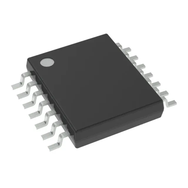
Texas Instruments MSP430F2012IPWR — Microcontrollers & Processors (MCU / MPU / DSP)

Texas Instruments MSP430F2012IPWR 16-bit MCU, 16 MHz

MPNMSP430F2012IPWR
Active

Texas Instruments MSP430F2xx series MSP430F2012IPWR, 16-bit MCU, 16 MHz, 2 KB Flash, 128 B RAM, I²C, SPI, 10-bit ADC, 14-TSSOP, -40°C to 85°C.

$3.1700Ref. price · indicative, final on quote
Packaging14-TSSOP (0.173", 4.40mm Width)
RoHSROHS3 Compliant
SeriesMSP430F2xx
Independent supplier — new & surplus stockAuthenticity-screened · ESD-safe packingListing updated Aug 2026

Specifications

MSP430F2012IPWR specifications
ParameterValue
SeriesMSP430F2xx
MountingSurface Mount
Oscillator typeInternal
Program memory typeFLASH
Voltage - supply (Vcc (Vdd))1.8V ~ 3.6V
Operating temperature-40°C~85°C(TA)
Speed16MHz
PackageTape & Reel (TR); Cut Tape (CT)
RAM size128 x 8
Core size16-Bit
PeripheralsBrown-out Detect/Reset, POR, PWM, WDT
ConnectivityI²C, SPI
Number of i (O)10
Core processorMSP430 CPU16
Case14-TSSOP (0.173\", 4.40mm Width)
Data convertersA/D 8x10b
Program memory size2KB (2K x 8 + 256B)

Product details

Industrial temperature grade and on-chip peripherals reduce BOM

The integrated peripherals — brown-out detect, POR, PWM, watchdog timer, I²C, SPI, and an 8-channel 10-bit ADC — cover the common interface and measurement needs for such applications without external chips. The internal oscillator further cuts external component count, though its accuracy should be verified against the application's timing budget.

Memory and speed: what the 2 KB Flash and 16 MHz mean for fit

The 2 KB Flash (2K x 8 plus 256 bytes) and 128 bytes of RAM are the hard constraints that define where this part works. A firmware engineer should budget the code size early: a bootloader, a simple state machine, and a few sensor reads will fit; a USB stack or a complex control algorithm will not. The 16 MHz clock provides adequate throughput for reading an I²C temperature sensor at 100 kHz or driving a PWM fan at 25 kHz, but it is not a number-crunching core. The 10-bit ADC with eight multiplexed channels samples at a rate suitable for slow analog signals — thermocouples, potentiometers, battery voltage monitoring — not high-speed data acquisition.

14-TSSOP footprint and surface-mount assembly

The tape-and-reel or cut-tape shipping options suit both prototyping and volume production.

Frequently asked questions

What is the difference between MSP430F2012IPWR and MSP430F2012IPW?

The suffix 'R' in MSP430F2012IPWR indicates tape-and-reel packaging, while the MSP430F2012IPW (without the 'R') typically ships in tubes or trays. The silicon, the 14-TSSOP package, and all electrical specifications are identical between the two order codes. The 'R' variant is the one you want for automated pick-and-place assembly.

Can I replace MSP430F2012IPWR with MSP430F2013IPWR?

The MSP430F2013IPWR is a pin-compatible upgrade within the same family — it doubles the Flash to 4 KB and the RAM to 256 bytes while keeping the same 14-TSSOP footprint, 16 MHz clock, and peripheral set. If your firmware fits in 2 KB, the MSP430F2012IPWR is the correct BOM choice; if you need more code space or working memory, the MSP430F2013IPWR is a drop-in replacement with no board layout change.

How do I program the MSP430F2012IPWR?

Programming is done through the Spy-Bi-Wire (SBW) two-wire JTAG interface, which uses the TEST and RST pins. Texas Instruments' MSP-FET or a compatible programmer/debugger connects to these pins. The on-chip Flash is in-system programmable, so no external programmer is needed for production programming — the SBW interface handles both programming and debug.