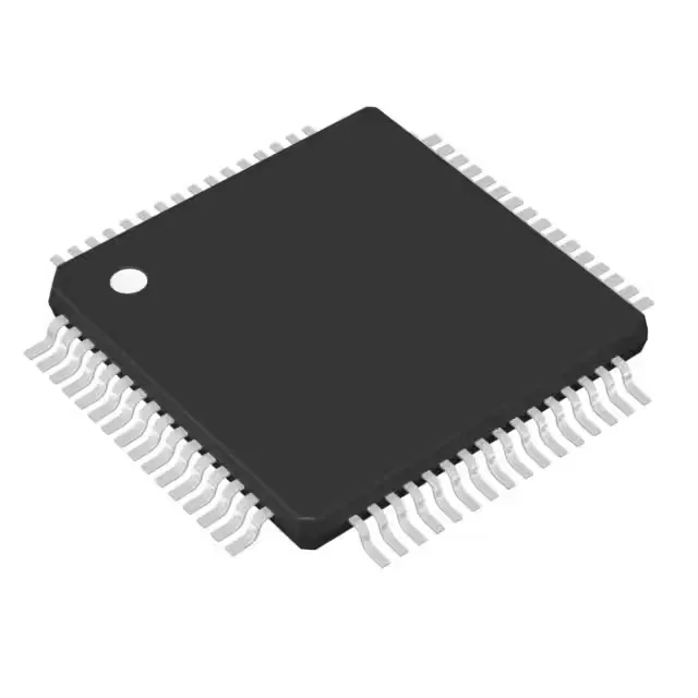
Mixed-signal MCU for sensor and control applications
It is housed in a 64-pin LQFP package (10x10 mm) and is intended for applications such as sensor signal conditioning, industrial control loops, portable instrumentation, and battery-powered data acquisition where low power and mixed-signal integration are priorities.
8 MHz core clock — timing budget for control loops
The 8 MHz clock speed defines the instruction throughput and interrupt latency for real-time tasks. At this frequency, the MSP430 CPU16 can execute most single-cycle instructions, giving a typical MIPS rate close to the clock. For a PID loop or sensor polling routine that needs to complete within a few microseconds, the 8 MHz ceiling means the firmware must be efficient — but it also keeps dynamic power low, which is the trade-off this family is designed for.
48 KB Flash and 10 KB SRAM — firmware and data buffer sizing
The 48 KB Flash (48K x 8 plus 256 bytes) is sized for moderate-complexity firmware: a bootloader, a real-time kernel, communication stacks, and application code. The 10 KB SRAM provides room for data buffers, stack, and DMA transfers. For designs that log sensor data or run a small RTOS, this memory partition is adequate — but if the application requires large lookup tables or extensive buffering, the 48 KB Flash may be the tighter constraint. The Flash is field-programmable, supporting in-system updates via the UART or SPI bootloader.
Integrated 12-bit ADC and DAC — analog front-end on-chip
The ADC can sample at rates sufficient for most sensor interfaces (temperature, pressure, current sense) without an external converter. The dual DACs are useful for generating analog setpoints or driving analog actuators. The 12-bit resolution gives 4096 steps, which is typical for industrial control and instrumentation — not high-precision metrology, but adequate for 0.1% accuracy with proper calibration.
The brown-out detect and POR circuits ensure reliable startup and reset under supply transients.
It is not subject to a last-time-buy or end-of-life notice.