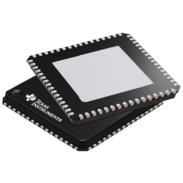
16-bit MCU for low-power control — MSP430F149IRTDT
It runs at 8 MHz and integrates 60 KB of Flash program memory plus 2K x 8 of RAM, with 48 general-purpose I/O lines. On-chip peripherals include POR, PWM, and WDT, along with SPI and UART/USART serial interfaces and an 8-channel 12-bit ADC.
The 8 MHz clock rate is the ceiling for this MSP430 CPU16 core. At this speed the part draws its active-mode current, which is typically in the hundreds of microamps per MHz range for the MSP430 architecture. If your application needs to run a real-time control loop with tight timing at, say, 20 kHz PWM update, the 8 MHz clock still leaves hundreds of cycles per update — but if you are doing heavy DSP or floating-point math, this is not the right core. The trade-off is that the low clock keeps power low, which is the whole point of the MSP430 family.
60 KB Flash and 2K x 8 RAM — sizing the firmware
The 60 KB Flash (organized as 60K x 8 plus 256 bytes) is a mid-range density for the MSP430x1xx series. It can hold a modest control firmware stack with a bootloader, a communication protocol handler (e.g., Modbus RTU over UART), and a sensor calibration table. The 2K x 8 RAM is tight — 2 KB — so any data buffering, such as a UART receive ring buffer or ADC sample FIFO, needs careful sizing. If your application requires large lookup tables or extensive data logging in RAM, you will either need to use the Flash for constant data or step up to a higher-RAM variant in the family.
The exposed pad is also the ground connection for the die, so it is not optional. Surface-mount assembly is standard; the package is MSL-rated per the TI datasheet (typically MSL 3, but verify the specific date code's moisture sensitivity level on the reel label).
The part is ROHS3 compliant.