8 MHz 16-bit core — what the speed means for your loop
The MSP430F1122IPWR runs the MSP430 CPU16 core at 8 MHz — this is the instruction-cycle ceiling. For a control loop reading one ADC channel, executing a PID calculation, and updating a PWM output, the total cycle budget is roughly 125 ns per instruction; a 50-instruction loop runs in 6.25 µs, leaving headroom for a 10 kHz update rate. If your application needs faster math or higher sensor throughput, this part hits its limit early. The 4 KB on-chip flash and 256 x 8 RAM are the hard memory boundary. A typical MSP430 firmware image with a UART bootloader, ADC driver, and basic state machine fits in about 2.5 KB — the remaining 1.5 KB is margin for feature creep. The 256 B RAM handles a 128-byte receive buffer plus 64 bytes of global variables; anything larger forces external SRAM or a different MCU.
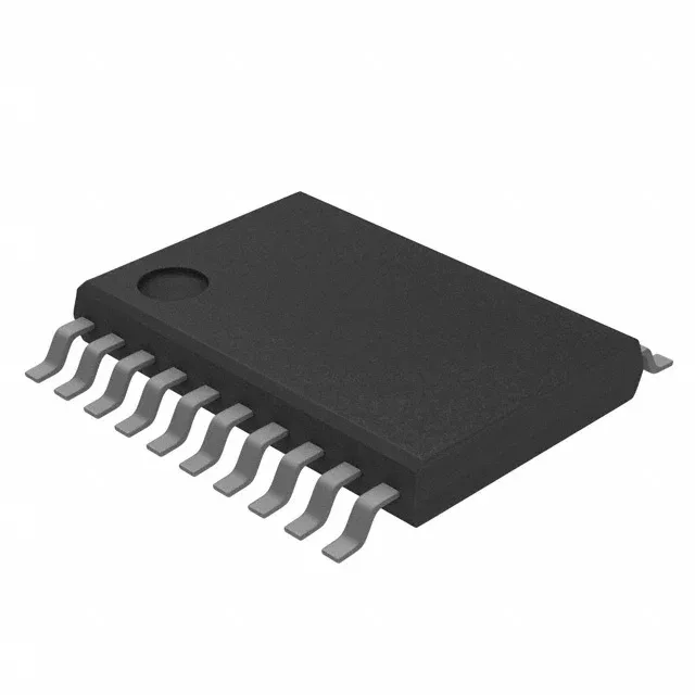
No exposed pad means the thermal path is through the leads — for continuous operation at 8 MHz with all I/O toggling, the junction temperature stays within the 85°C limit as long as the ambient is below 70°C in still air.
Active lifecycle — no end-of-life pressure
The base product number MSP430F1122 spans multiple package variants (TSSOP, QFN) and tape/reel options; the IPWR suffix specifies the 20-TSSOP on tape-and-reel. If your pick-and-place line is set for 20-TSSOP, this is the correct reel variant. No cross-reference or second-source is registered — the part is single-sourced from TI.
ADC and I/O — what the 14 pins actually give you
Eight 10-bit ADC channels are multiplexed onto the analog input pins. At 8 MHz core clock, the ADC samples at about 200 ksps — enough for reading eight thermocouple channels at 25 Hz each, or a single vibration sensor at 20 kHz. The 10-bit resolution (1024 counts) gives 4.9 mV per step on a 5 V reference; for a 0-100°C temperature sensor with 10 mV/°C output, that is 0.5°C per LSB — adequate for process monitoring but not precision metrology. 14 general-purpose I/O pins are available, shared with the ADC inputs, UART, and timer outputs. In a typical deployment with one UART (TX/RX = 2 pins), one PWM output (1 pin), and two external interrupts (2 pins), the remaining 9 pins cover digital sensors or pushbuttons. If your BOM calls for more than 14 I/O, an external port expander or a larger MSP430 variant is needed.
Sourcing posture — quoted to order
This is an active, in-production Texas Instruments MCU.