What the 1.5 A switch means in a boost LED driver
The LP5526TL/NOPB is a DC-DC boost regulator with an integrated 1.5 A switch, so the inductor and external diode see the full switch current — the 1.5 A rating sets the ceiling for the LED string current times the duty cycle. For a typical 20 V output from a 3.6 V input, the average inductor current is roughly 5.5× the LED current, meaning the per-channel LED current stays well under 300 mA even with all five outputs active.
Five outputs with PWM dimming — how the topology works
Five independent current sinks, each dimmable via PWM on the enable pin, let you drive separate LED strings for backlight and camera flash from the same boost rail. The boost output voltage is regulated between 8 V and 20 V, set by an external resistor divider, so the headroom for each string is determined by the highest-Vf LED plus the sink dropout. The internal switch handles the boost inductor current directly — no external FET needed — which simplifies the BOM but means the total LED power is limited by the 1.5 A switch rating and the thermal dissipation of the 25-uSMD package.
Package and board-fit: 25-WFBGA / 25-uSMD
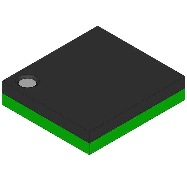
The LP5526TL/NOPB comes in a 25-bump WFBGA (0.50 mm pitch) that is also designated as the 25-uSMD supplier device package. The fine-pitch BGA requires a 4-layer PCB with microvias for fan-out — two-layer boards will struggle to route the five LED cathodes, the boost inductor connection, and the feedback trace without via-in-pad. The small footprint (roughly 3 mm × 3 mm) saves board area but demands careful thermal management: the center bumps carry ground and the switch current returns through the PCB copper. A 2 oz copper pour on the top layer under the package helps spread the heat.