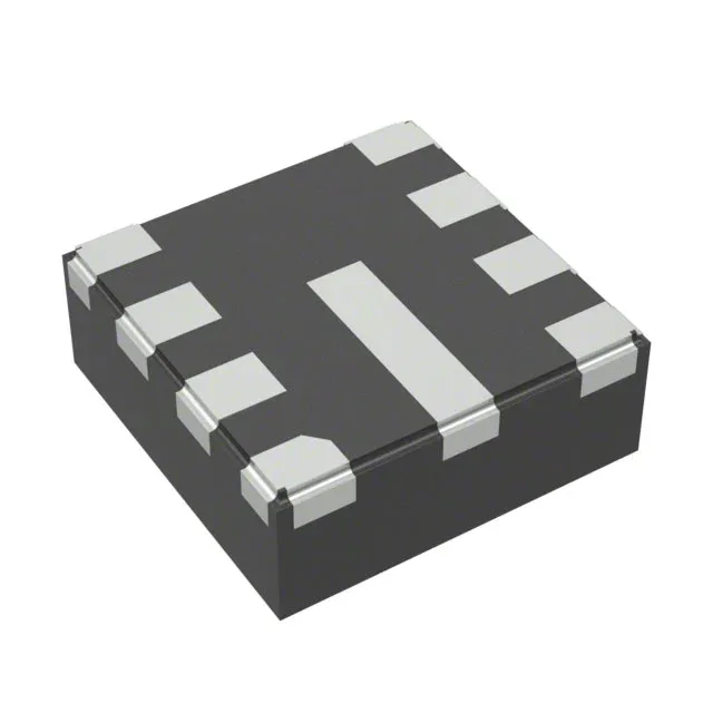
Texas Instruments LMR36506R5RPER — Discrete Semiconductors

TI LMR36506R5RPER 5V 600mA Buck Converter, 65V Input, 9-VQFN

MPNLMR36506R5RPER
End of Life

Texas Instruments LMR36506R5RPER SIMPLE SWITCHER® step-down buck converter, 5V fixed output, 600mA, 3V-65V input, 200kHz-2.2MHz, synchronous rectifier, 9-VQFN-HR (2x2mm) wettable flank, -40°C to 150°C.

$4.15Ref. price · indicative, final on quote
Packaging9-VFQFN
RoHSNot applicable
Independent supplier — new & surplus stockAuthenticity-screened · ESD-safe packingListing updated Aug 2026

Specifications

LMR36506R5RPER specifications
ParameterValue
Output typeFixed
MountingSurface Mount, Wettable Flank
Voltage - input65V
Voltage - output (Min (Fixed))5V
Output current600mA
Frequency - switching200kHz ~ 2.2MHz
I/O channels1
Operating temperature-40°C ~ 150°C (TJ)
PackageTape & Reel (TR); Cut Tape (CT)
FunctionStep-Down
TopologyBuck
Case9-VFQFN
Output configurationPositive
Synchronous rectifierYes

Product details

Wide-VIN buck for 12/24/48 V industrial rails

The LMR36506R5RPER is a 600 mA synchronous step-down regulator from TI's SIMPLE SWITCHER family, accepting 3 V to 65 V input and delivering a fixed 5 V output. That 65 V ceiling covers 48 V nominal telecom supplies with margin for transients, and the 3 V minimum lets it start from a deeply-discharged 12 V battery or a 5 V pre-regulated rail. The 600 mA continuous output suits sensor modules, I/O isolators, and auxiliary housekeeping rails in motor drives or PLC racks where the main load is a few hundred milliamps. The synchronous rectifier keeps efficiency above 90 % down to light loads, which matters when the converter idles between burst reads from a fieldbus transceiver.

Switching frequency and thermal envelope

At the low end you minimise switching losses for a 48 V input; at the high end you shrink the inductor to 2.2 µH or 3.3 µH, which fits the 2×2 mm package profile. The 150 °C junction temperature rating gives headroom in a sealed enclosure with 85 °C ambient and no forced air — the thermal pad under the 9-VQFN-HR carries the heat into the PCB copper pour. The fixed 5 V output eliminates the feedback divider and the associated noise injection on the sense node — one less component to place in the tight layout around the 2 mm QFN.

The 9-VQFN-HR (2×2 mm) package with wettable flanks supports automated optical inspection (AOI) of the solder joints — no hidden fillets under the body. The exposed thermal pad is on the bottom; the recommended PCB land pattern includes a 2.2×2.2 mm thermal pad with at least four vias to the inner ground plane. Available in Tape & Reel (TR) and Cut Tape (CT) options for prototype or production quantities.

Frequently asked questions

What is the closest functional second-source to LMR36506R5RPER?

The LMR36506RF3RPER is the same 600 mA synchronous buck converter in the same 9-VQFN-HR package, but with a fixed 3.3 V output instead of 5 V. The pinout and footprint are identical — the only difference is the output voltage set by the internal feedback. For a 5 V rail the LMR36506R5RPER is the direct fit; the adjustable-output sibling LMR36506RRPER (1 V to 65 V via external divider) covers non-standard voltages.

Will LMR36506R5RPER drop into a board designed for LMR36506RF3RPER?

Yes, the two parts share the same package (9-VQFN-HR, 2×2 mm), pinout, and external component values (inductor, input/output capacitors, frequency-set resistor). The only change is the output voltage — 5 V vs 3.3 V — so the load circuitry must be rated for 5 V. No PCB layout change is needed.