AEC-Q100 buck controller for 65 V rails
The LM5117QPSQE/NOPB: The 5.5 V to 65 V input span means it starts from a cold-crank 12 V battery dipped below 6 V and survives a 60 V load-dump transient without an external clamp. Single-phase output drives an external N-channel FET pair in synchronous rectification configuration. The 200 kHz or 480 kHz switching frequency is set by a single resistor; the ramp and soft-start pins give the designer independent control over slope compensation and inrush current limiting.
Wide-VIN design and switching-frequency trade-offs
The 65 V abs-max supply rating is the headline figure, but the practical operating envelope is set by the thermal dissipation in the external MOSFETs and the inductor core losses at the chosen switching frequency. At 480 kHz the magnetics shrink — smaller inductor footprint — but the gate-drive losses in the FETs climb; at 200 kHz the efficiency peaks but the inductor is roughly double the volume. The controller itself draws its gate-drive current from the VCC pin, so the bias supply needs to deliver that peak current without droop. Synchronous rectification eliminates the Schottky catch diode — the low-side FET conducts during the off-time. This buys a few points of efficiency at heavy load but demands dead-time control to prevent shoot-through. The LM5117 integrates adaptive dead-time; still, the layout must keep the high-side and low-side gate-return loops tight to the source of each FET.
Package and thermal interface
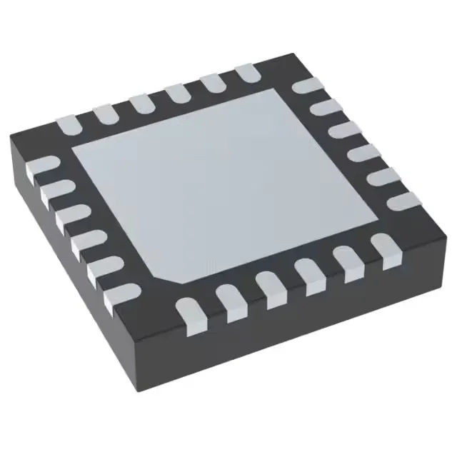
24-lead WQFN with exposed pad, 4 mm × 4 mm body. Without that via array the junction-to-board thermal resistance climbs and the 125 °C rating becomes academic above 1 A switching current. The 0.50 mm pitch demands a solder-mask-defined pad with a 0.25 mm stencil aperture for the perimeter pins. The exposed pad aperture should be 3.6 mm × 3.6 mm with a 70-80% solder-paste coverage pattern to avoid voiding under the die attach.
Available to order against an RFQ; current pricing and lead time confirmed at quote time. The AEC-Q100 qualification documentation and the full datasheet with application curves accompany the shipment.