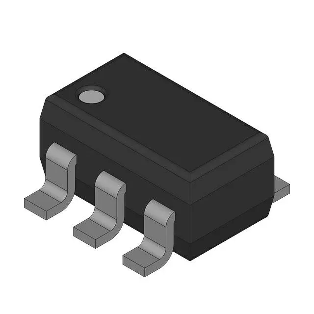
The LM4128DMF-3.0 is a series voltage reference from TI's LM4128 family, delivering a fixed 3V output with ±1% initial accuracy. That ±1% tolerance means the output sits between 2.97V and 3.03V at 25°C — tight enough to serve as the reference for an 8-bit or 10-bit ADC without external trimming, but not sufficient for a 12-bit system that typically needs ±0.1% or better. Input voltage range is 2.2V to 5.5V, so it runs from a 3.3V rail with 300 mV headroom or from a 5V rail with 2V of dropout margin. The 20 mA output current ceiling limits the load to a single ADC reference input or a few op-amp bias networks — not enough to power a sensor bridge directly.
Temperature drift and noise floor — industrial-grade stability
That drift budget is acceptable for an industrial controller monitoring a 0-10V analog input with 8-bit resolution, but marginal for a 10-bit sensor front-end that needs to hold accuracy across a hot enclosure. For a 10-bit ADC with a 3V reference, the LSB is 2.93 mV, so the noise floor sits at about 10% of one LSB and does not limit resolution. For a 12-bit system (732 µV LSB), the noise is 39% of one LSB and starts to degrade the effective number of bits.
Active lifecycle, but RoHS non-compliant — what that means for procurement
RoHS compliance is marked as non-compliant. This part contains lead (Pb) above the 0.1% threshold — likely in the solder plating or the die-attach material. It is exempt under certain RoHS categories (e.g., Annex III exemption 7(c)-I for high-melting-temperature solders), but a BOM that requires full RoHS conformity cannot use this order code. The lead-free variant in the same family would carry a different suffix.
SOT-23-5 footprint and supply current — board-fit and power budget
The part is supplied in a SOT-23-5 package (SC-74A, SOT-753), 5-lead surface-mount with 0.95 mm pitch. The footprint is standard for small-signal references and fits a 2-layer PCB with basic fan-out. No exposed pad — thermal dissipation is through the leads and the board copper. Quiescent supply current is 100 µA typical. In a battery-powered sensor node that sleeps most of the time, the reference's own draw is the dominant idle current — the 100 µA floor means the reference cannot be left powered continuously in a sub-10 µA sleep budget design without a load switch.