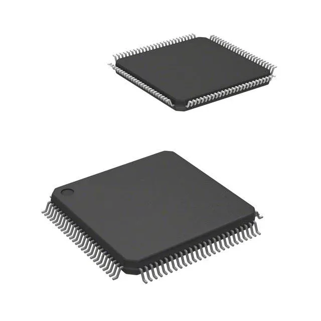
Cortex-M3 at 50 MHz — what the clock buys you
The LM3S8730-IQC50-A2 runs a 32-bit ARM Cortex-M3 core at 50 MHz — that is the single-cycle multiply and 12-cycle divide ceiling for the control loop. For a CANopen or Modbus TCP stack, the 50 MHz clock keeps the interrupt latency under 12 core cycles (240 ns at 50 MHz) before the vector table dispatches the handler.
Flash and RAM budget — what 128 KB / 64 KB means for the firmware build
128 KB of on-chip Flash (program memory type) and 64 KB of SRAM — the 64 KB RAM is split into a single 64K x 8 block. A typical Ethernet + CAN stack with a lightweight RTOS (FreeRTOS or TI-RTOS) leaves roughly 30–40 KB for application heap and stack after the TCP/IP and CANopen buffers are allocated. The Flash holds the bootloader, the stack image, and about 80 KB of application code before you hit the linker script ceiling. That saves two pins on the 100-LQFP package, but the oscillator accuracy (±1% typical over temp) limits the Ethernet PHY to 100BASE-TX where the clock recovery tolerates the drift; for precision timing, an external 25 MHz crystal feeds the PLL directly.
Peripheral mix — Ethernet, CAN, and serial interfaces on one die
Connectivity includes CANbus, Ethernet, I²C, IrDA, Microwire, SPI, SSI, and UART/USART — the Ethernet MAC with integrated 10/100 PHY and the CAN 2.0B controller share the same die. For a gateway board bridging a CAN fieldbus to an Ethernet backbone, this part eliminates the external PHY and CAN transceiver cost, but the 32 I/O pins must be multiplexed among the peripherals; the Ethernet and CAN pins are fixed, so the remaining 22 GPIOs serve the serial buses and discrete signals.
Supply rail and temperature range
The core and I/O share the same supply; there is no separate I/O rail.
Texas Instruments lists the LM3S8730-IQC50-A2 as Obsolete. No last-time-buy window remains open.