What this Stellaris MCU brings to a control board
It runs at 50 MHz from a single-core Cortex-M3 processor, with 256 KB of program Flash and 64 KB of SRAM — enough headroom for a modest RTOS, a CANopen stack, and a few PID loops without external memory.
The 50 MHz clock rate on this Cortex-M3 delivers around 1.25 DMIPS/MHz, so roughly 62.5 DMIPS peak. That is enough to run a field-oriented control (FOC) commutation loop for a single PMSM motor at 10–20 kHz PWM update rate, or to service a CAN message every 100 µs while keeping the UART logging and GPIO toggling alive. The 64 KB SRAM means you are not going to run a heavy GUI or a large data logger, but it holds a couple of 1 KB CAN buffers, a 4 KB RTOS heap, and a 16 KB stack partition without thrashing. The 256 KB Flash fits a FreeRTOS image plus a moderate application binary — leave room for a bootloader and a fallback image if you plan OTA updates.
Peripheral set — CAN, UART, SPI, and the rest
The LM3S2911 integrates a CANbus controller, multiple UART/USART channels, I²C, SPI, SSI, Microwire, and IrDA — a broad enough serial complement to bridge a CAN-based machine network to a local RS-485 or RS-232 debug port, or to talk to an external ADC/DAC over SPI while logging to a serial console. The 60 GPIO lines give you room for a parallel LCD interface, a keypad matrix, and a handful of status LEDs without a port expander.
For an existing BOM that already qualifies this MCU, the only sourcing path is the independent distribution market: broker inventory, surplus stock, or customer returns that have been tested and verified.
Package and footprint — what the 100-LQFP needs
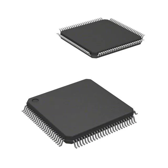
The 100-LQFP (14x14 mm) is a standard fine-pitch QFP with 0.5 mm lead pitch. It is a hand-solderable package for rework — a decent hot-air station with a fine nozzle and some flux can remove and replace it without a preheater, though the 100-pin count means careful alignment. The exposed thermal pad on the underside (if present on this variant — confirm from the mechanical drawing) should be stitched to a ground-plane copper pour with at least nine thermal vias if you plan to run the core above 60°C ambient at full clock. Decouple with a 10 µF ceramic bulk plus a 100 nF per VDD pair, placed within 3 mm of the pin.