Obsolete — what that means for your BOM
The LM3S2139-EQC25-A2: Quantities are lot-specific; we confirm availability and pricing at RFQ time against your target quantity.
Core and memory — what fits where
The ARM® Cortex®-M3 core runs at 25 MHz — this is the instruction throughput ceiling for the single-cycle multiply and hardware divide. The 64 KB of on-chip Flash (64K x 8) and 16K x 8 SRAM set the application footprint: a modest RTOS with a CAN stack and a few peripheral drivers fits, but a full TCP/IP stack with a large buffer pool will strain the RAM budget. Program memory is Flash, not OTP or ROM — field firmware updates are possible over the CAN or UART bootloader, provided the update image fits within the 64 KB boundary.
Peripherals and connectivity for control applications
The on-chip peripheral set includes CANbus, I²C, SPI, SSI, UART/USART, and IrDA — enough serial interfaces to talk to a motor drive over CAN, log data over UART, and read a sensor over I²C simultaneously. The 56 general-purpose I/O pins are multiplexed with these serial functions, so the usable I/O count depends on which peripherals are enabled. A 4-channel 10-bit ADC is integrated for analog feedback — reading a potentiometer, a current-sense resistor, or a temperature sensor without an external converter. The internal oscillator saves a crystal on the BOM, though the accuracy is adequate for UART baud-rate generation, not for precision timing. Brown-out detect, POR, and a watchdog timer are built in — the MCU can reset itself on a supply dip or a firmware hang without external supervisor ICs.
Package, supply, and temperature grade
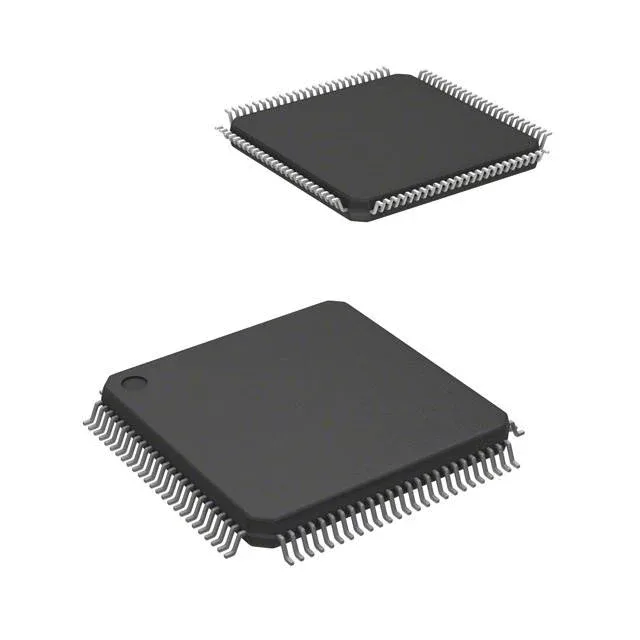
Housed in a 100-LQFP (14x14 mm) body with 0.5 mm pitch — a standard 4-layer board with via-in-pad is not required, but the fine pitch demands careful solder-paste stencil design and a clean reflow profile. The supplier device package is 100-LQFP (14x14). The I/O pins are not 5 V tolerant; level translation is needed if interfacing with 5 V logic or sensors.