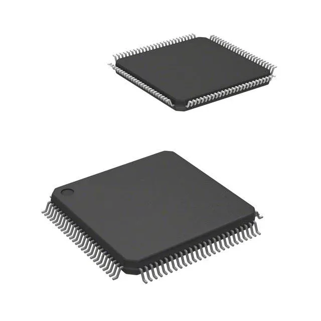
25 MHz Cortex-M3 with 64 KB flash — the BOM-fit ceiling
The LM3S1110-IQC25-A2T is a Stellaris® ARM® Cortex®-M3S 1000 series 32-bit MCU running at 25 MHz. With 64 KB of program flash and 16 KB of SRAM, this part sits at the entry point of the Stellaris 1000 family — enough memory for a modest control loop, a UART-based fieldbus stack, and a few hundred lines of application code before the flash fills. The 2.25 V to 2.75 V supply rail is narrower than the 3.3 V typical for Cortex-M3 parts of this era — the board's regulator must hold within that band, or the internal POR brown-out detect resets the core.
41 general-purpose I/O are brought out to the 100-LQFP package — enough to drive a character LCD, read a keypad matrix, and still leave pins for the SSI/SPI and UART peripherals. The connectivity block includes IrDA, Microwire, SPI, SSI, and UART/USART, so the part can talk to a serial EEPROM, a radio module, and a host controller on separate buses without external muxing. On-chip peripherals include a PWM generator, a watchdog timer, and brown-out detect/reset — the WDT and BOD are safety-critical for an unattended controller that must self-recover after a supply glitch. The internal oscillator eliminates the external crystal for the core clock, saving two pins and a few cents on the BOM, though the accuracy is limited to the trimmed RC tolerance.
NRND lifecycle — what it means for the BOM line
Texas Instruments lists the LM3S1110-IQC25-A2T as NRND (Not Recommended for New Designs). The part is still orderable for existing production, but TI will not qualify it for new sockets — a last-time-buy window is the normal next step when the NRND flag has been set. For a line already using this MCU, the immediate concern is securing enough inventory to cover the remaining build horizon before the EOL notice arrives. The Stellaris family was migrated to the Tiva C series, but the supply voltage and pinout differ — a board spin is required for any replacement. Sourced through independent distribution against an RFQ; availability and pricing confirmed at quote time.
Package and board-fit checklist
The 100-LQFP package (14x14 mm body, 0.50 mm pitch) demands a 4-layer PCB for reliable fan-out — two-layer boards will struggle to route all 41 I/O plus the supply and ground traces. The exposed paddle on the bottom of the QFP is the primary thermal path; a 2x2 array of vias under the pad to an internal ground plane keeps the junction temperature below the 85°C ceiling when the core is running at full clock. Surface-mount only — no through-hole variant exists. The tape-and-reel packaging means the part feeds into a pick-and-place line without a reel change for the 100-LQFP feeder.