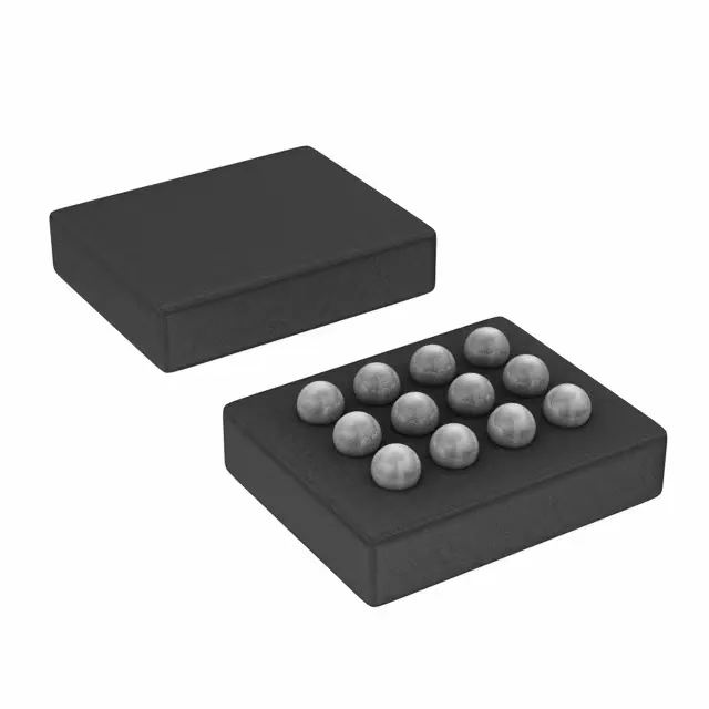
12-DSBGA footprint and board integration
The LM3643AYFFR comes in a 12-bump DSBGA (12-DSBGA) package — 0.4 mm pitch, no leads, the bumps are the terminals. That means the board needs a stencil with small apertures and a reflow profile tuned for the solder paste volume; no hand-soldering this one in the field. The 12-DSBGA supplier device package is the same as the case code, so the footprint in the datasheet is the one to use. Surface-mount only, and with a 0.4 mm pitch the PCB layout has to keep the traces short between the inductor and the output caps to minimise loop inductance at 4 MHz switching.
Dual 1.9 A boost for camera flash
This is a step-up (boost) regulator with two outputs, each capable of 1.9 A peak switch current. That 1.9 A per channel is the switch limit, not the LED current — the actual LED current depends on the sense resistor and the boost ratio, but the part can drive a pair of high-current flash LEDs from a battery that is lower than the LED forward voltage. The 4 MHz switching frequency keeps the inductor small, which matters when the whole flash subassembly has to fit behind a camera lens. Dimming is over I²C, so the host processor sets the flash current and timing digitally — no external PWM pin needed.