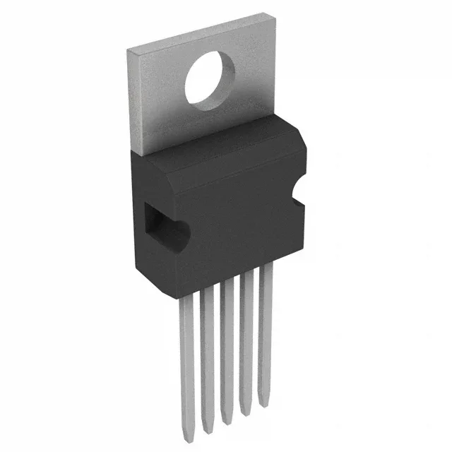
The Texas Instruments LM2576T-ADJ/NOPB is a SIMPLE SWITCHER monolithic step-down (buck) regulator in a TO-220-5 through-hole package, rated for 3 A continuous output and switching at 52 kHz. The adjustable output version covers 1.23 V to 37 V from a 4 V to 40 V input, making it a single-BOM-line fit for 3.3 V logic rails, 5 V MCU supplies, 12 V industrial bus power, or 24 V auxiliary rails.
52 kHz switching — inductor sizing and ripple trade-off
At 52 kHz the LM2576T-ADJ/NOPB uses a larger inductor than a modern 500 kHz+ switcher — typically 100 µH to 330 µH for a 3 A design — but the lower frequency reduces switching losses and eases layout constraints on the switch node. The trade-off is higher output ripple amplitude at the fundamental, which the output capacitor bank filters. For a 5 V / 3 A rail the ripple stays under 50 mV p-p with a 330 µH inductor and 330 µF output cap per the typical application; the BOM cost engineer should budget for a through-hole or surface-mount power inductor rated for the DC current without saturation.
Through-hole TO-220-5 — heatsink and board-mount reality
The TO-220-5 package has an exposed metal tab that must be soldered or bolted to a heatsink or PCB copper plane for any load above 1 A. At 3 A output with a 12 V-to-5 V conversion the die dissipates roughly 5 W; without a heatsink the junction hits 125°C at 50°C ambient, leaving no margin. The through-hole leads require a 0.100-inch pitch pattern on the board — standard for TO-220 footprints — and the tab hole accepts a #6 screw for mechanical retention and thermal transfer.
The base product number LM2576 spans multiple fixed-output voltage variants (3.3 V, 5 V, 12 V, 15 V) and the adjustable version, all in the same TO-220-5 footprint — the BOM can mix fixed and adjustable rails from a single distributor line item.
No synchronous rectifier — external Schottky diode required
The LM2576T-ADJ/NOPB does not integrate a synchronous rectifier. The external catch diode — typically a 3 A, 40 V Schottky like the 1N5822 or MBR340 — must be placed close to the IC's switch and ground pins to minimise loop inductance. The diode forward voltage and reverse leakage add to the total loss; at 3 A output the diode dissipates roughly 1.5 W, so a heatsink or adequate PCB copper area is needed for it as well.