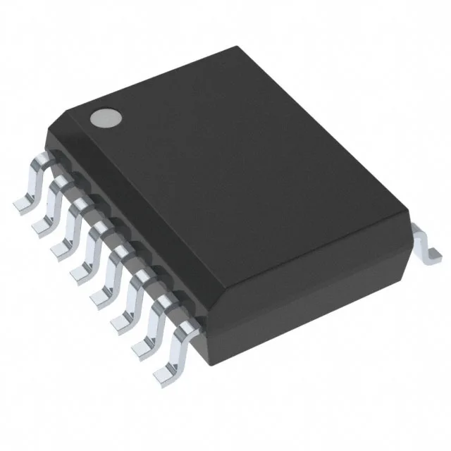
Quad-channel capacitive isolator for industrial signal isolation
Its 25 Mbps data rate and 42 ns max propagation delay suit it for isolating SPI, UART, and general-purpose logic-level interfaces in motor drives, PLC I/O modules, and industrial fieldbus nodes.
25 Mbps with 42 ns propagation delay — timing budget for isolated links
At 25 Mbps the part handles a 40 ns bit period, and the 42 ns max propagation delay (tpLH / tpHL) means the total loop delay for a single direction is just over one bit time. That matters for SPI clock rates above 10 MHz where the master expects data back within a half-cycle — the designer needs to account for the isolator delay in the timing closure. The 2.5 ns max pulse-width distortion keeps the duty-cycle error small enough for UART framing at 115200 baud without bit-slip.
2500 Vrms isolation and 25 kV/µs CMTI — noise rejection in harsh environments
Rated for 2500 Vrms basic isolation per the device class, with a minimum common-mode transient immunity of 25 kV/µs. That CMTI figure is the key spec for motor-drive applications where the inverter switching generates fast common-mode voltage swings on the bus — if the isolator cannot reject those edges, data corrupts. The 2 ns typical rise/fall time keeps the output edges clean enough for the downstream logic without excessive ringing.
Channel configuration: three inputs on side 1, one on side 2
The channel direction map is 3/1 — three channels drive from side 1 to side 2, one channel drives from side 2 to side 1. That asymmetric layout fits the common industrial pattern where a microcontroller on side 1 sends multiple control signals (chip select, clock, data) across the barrier and receives a single feedback or data-ready signal back. The unidirectional channel type means each channel is fixed-direction, so the designer must match the signal flow to the pin assignment before layout.