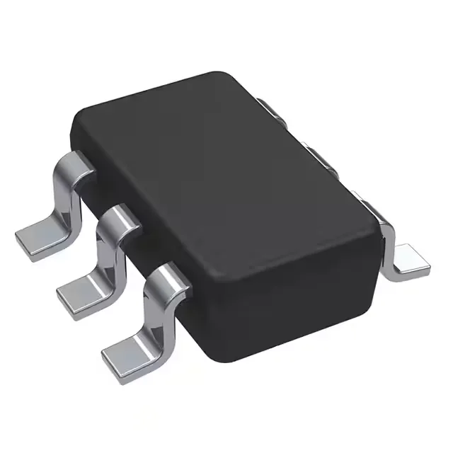
Texas Instruments INA181A4QDBVRQ1 — Analog & Data Acquisition

INA181A4QDBVRQ1 Current Sense Amplifier, AEC-Q100, 105 kHz

MPNINA181A4QDBVRQ1
End of Life

Texas Instruments INA181A4QDBVRQ1, automotive AEC-Q100 current sense amplifier, single circuit, rail-to-rail output, 105 kHz gain bandwidth, 2 V/µs slew rate, 2.7-5.5 V supply, SOT-23-6 package, -40 to 125°C.

$0.66Ref. price · indicative, final on quote
PackagingSOT-23-6
RoHSROHS3 Compliant
SeriesAutomotive, AEC-Q100
Independent supplier — new & surplus stockAuthenticity-screened · ESD-safe packingListing updated Aug 2026

Specifications

INA181A4QDBVRQ1 specifications
ParameterValue
SeriesAutomotive, AEC-Q100
Output typeRail-to-Rail
MountingSurface Mount
Amplifier typeCurrent Sense
Voltage - input offset100 µV
Voltage - supply span5.5 V
Current - supply195µA
Current - input bias75 µA
Current - output (Channel)8 mA
Operating temperature-40°C ~ 125°C (TA)
Gain bandwidth product105 kHz
PackageTape & Reel (TR); Cut Tape (CT)
Slew rate2V/µs
CaseSOT-23-6
Number of circuits1

Product details

What this current sense amplifier does on the board

The 105 kHz gain-bandwidth product means it can track DC load changes and low-frequency ripple, but it won't resolve switching edges in a PWM drive above a few kHz. That's fine for overcurrent detection and average-current feedback loops.

Gain-bandwidth product is 105 kHz and slew rate is 2 V/µs. The rail-to-rail output uses the full ADC input range.

Supply and quiescent current

Quiescent current is 195 µA typical.

Frequently asked questions

Is INA181A4QDBVRQ1 equivalent to INA181A4IDBVR?

The INA181A4QDBVRQ1 is the automotive-qualified (AEC-Q100) version of the INA181A4IDBVR. The non-Q version lacks the automotive temperature range and qualification. Functionally they are the same current sense amplifier, but the Q-suffix part is specified for -40°C to 125°C operation and is built to automotive reliability standards.

What is the pinout of INA181A4QDBVRQ1?

The INA181A4QDBVRQ1 comes in a SOT-23-6 package. Pin 1 is the output, pin 2 is GND, pin 3 is the negative input, pin 4 is the positive input, pin 5 is V+, and pin 6 is the reference voltage input. The pin 1 indicator is a dot on the top of the package.