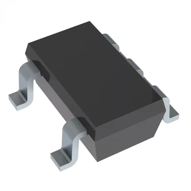
Current-sense amplifier for low- and high-side monitoring
It is a member of the INA180 family, which offers fixed gains; the A4 variant provides a gain of 100 V/V. The part operates from a 2.7 V to 5.5 V supply span and delivers a rail-to-rail output, making it suitable for both low-side and high-side sensing in 3.3 V and 5 V systems. With a -3 dB bandwidth of 350 kHz and a slew rate of 2 V/µs, it can track current waveforms in DC/DC converters, motor drives, and solenoid loads. Housed in a SOT-23-5 package, it fits compact PCB layouts in industrial control, automotive, and power-management applications.
The 350 kHz -3 dB bandwidth sets the highest-frequency current ripple or transient the amplifier can reproduce with reasonable accuracy. For a typical buck converter switching at 500 kHz, the fundamental and first few harmonics fall within this band, so the output waveform will reflect the average current and ripple envelope. If you are sensing fast overcurrent events (e.g., short-circuit detection in a motor driver), verify that the amplifier's response time meets your protection-latch timing budget.
The rail-to-rail output lets the amplifier swing close to both supply rails, maximizing the usable output voltage range for a given shunt drop. At a 3.3 V supply, a 100 mV shunt signal (gain of 100 V/V) produces a 10 V output — but the output cannot exceed 3.3 V, so the shunt voltage must be scaled to keep the output within the rail. The 2.7 V minimum supply allows operation from a 3.3 V rail with margin, and the 5.5 V maximum covers 5 V ±10% systems. This part is not intended for 12 V or higher rails without external attenuation.
The 125°C maximum junction temperature allows placement near hot power stages or in engine-bay electronics, provided the PCB thermal management keeps the die within limits. The SOT-23-5 package has a moderate thermal resistance; for continuous high-side sensing at elevated ambient, check the power dissipation against the derating curve in the datasheet.
It is RoHS3 compliant.