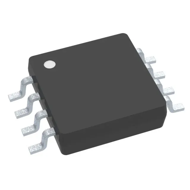
Precision differential front-end for sensor conditioning
The Texas Instruments INA126EA/250 is a single-supply instrumentation amplifier in an 8-VSSOP package, designed to extract small differential signals from noisy common-mode environments — the classic role for bridge sensors, thermocouple interfaces, and medical instrumentation front-ends.
Low quiescent current and DC accuracy trade-offs
At 175 µA supply current, the INA126EA/250 suits loop-powered 4-20 mA transmitters and battery-operated data loggers where every microamp counts. The 10 nA input bias current is typical for a bipolar-input instrumentation amplifier; designs with source impedances above 100 kΩ should budget for offset drift from bias current mismatch.
The -3 dB bandwidth of 200 kHz and slew rate of 0.4 V/µs define the large-signal and small-signal response: expect full-power bandwidth around 6 kHz at 10 V output swing, so this part is a DC-to-low-frequency precision amplifier, not a high-speed data acquisition front-end. Output current capability of 10 mA per channel is sufficient to drive a typical ADC input or a twisted-pair cable up to a few metres; for heavier loads (e.g., 50 Ω terminated lines) an external buffer is needed.