5.4 GHz bandwidth — the signal-integrity floor
The HD3SS460RHRR: The -3 dB bandwidth is rated at 5.4 GHz. That covers the 5 Gbps signaling rate of USB 3.2 Gen 1 with margin and reaches into Gen 2 (10 Gbps) territory — the insertion loss through the mux stays flat across the fundamental and second harmonic of a 5 Gbps PRBS pattern. The 14 Ohm max on-state resistance contributes to the channel's total series resistance. In a typical USB-C cable plant with 10-15 mOhm per inch of trace, the mux adds roughly 1 dB of resistive loss at DC — negligible against the cable's skin-effect roll-off at 2.5 GHz.
4:6 switching matrix — what the mux actually does
The multiplexer/demultiplexer circuit is 4:6. Four differential lanes on the host side (two TX, two RX) are switched to six differential lanes on the connector side — the extra two lanes map to the USB-C receptacle's sideband-use (SBU) or alternate-mode (DisplayPort) pins. The bi-directional feature means any lane can carry traffic in either direction, so the mux handles cable flip without a separate orientation switch.
28-WFQFN — package and board-fit
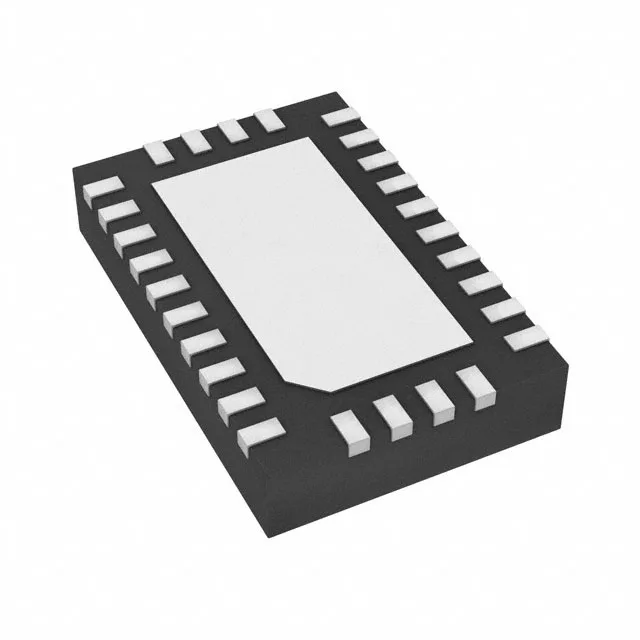
The 28-WFQFN Exposed Pad measures 5.5 mm × 3.5 mm. The 0.5 mm pitch demands a 4-layer board for clean fan-out; a 2-layer board will struggle to route the differential pairs out of the inner rows without impedance discontinuities.