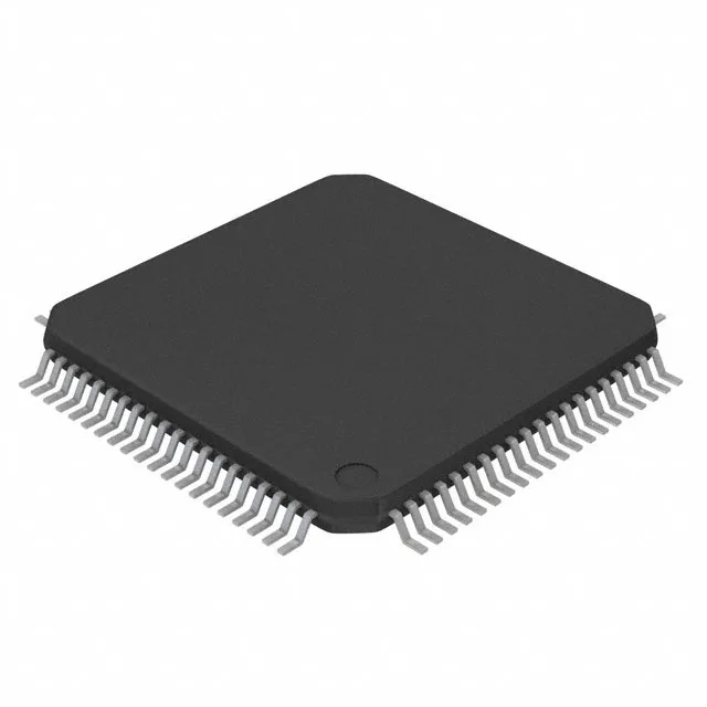
100 MHz C28x core for real-time control loops
The F2800132PTR: That clock rate determines the PWM update frequency and control-loop bandwidth — for a typical motor-field-oriented control (FOC) loop with a 16 kHz current loop and 4 kHz speed loop, the 100 MHz core leaves enough headroom for the control algorithm, comms stack, and fault handling without cycle-counting. On-chip memory consists of 64 KB (32K x 16) flash and 18K x 16 RAM — sufficient to hold a single motor-control firmware image with lookup tables and a modest data buffer, avoiding external memory in a compact drive or inverter design.
Analog front-end: 17-ch ADC and 8-ch DAC
The part integrates a 17-channel 12-bit SAR ADC and an 8-channel 12-bit DAC. The ADC channels can sample phase currents, DC-bus voltage, and temperature from a three-phase inverter with enough margin to leave a few channels for auxiliary sensors. The DAC outputs serve as setpoint references or analog telemetry without an external converter. Operating temperature spans -40 to +125 °C (TA), qualifying the MCU for industrial motor-drive cabinets and under-hood automotive environments where ambient heat rises above 85 °C.
Connectivity and peripherals for fieldbus integration
On-chip brownout detect, POR, PWM, and WDT reduce the external supervisor and timer IC count on the board.
Package and board integration
The 0.5 mm pitch LQFP footprint routes cleanly on a 4-layer board with the core supply and analog rails on inner planes.
It is ROHS3 compliant, with no restricted substances in the package or plating.