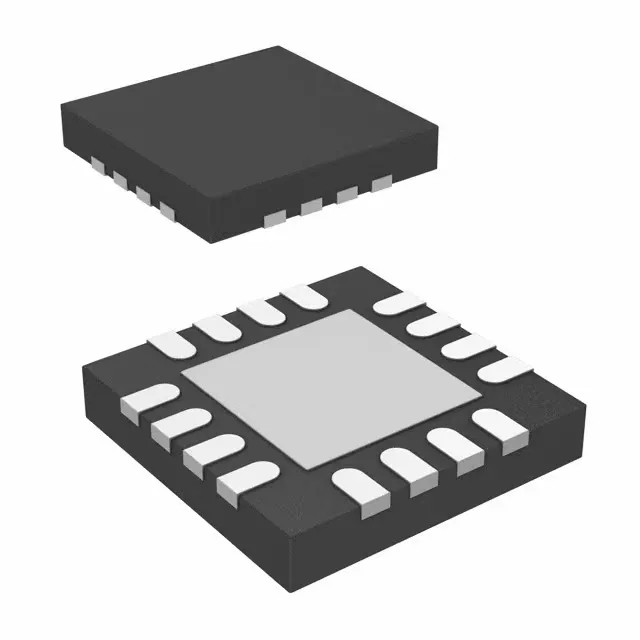
Texas Instruments DRV8833RTYR — Power Management (PMIC / Gate Driver)

DRV8833RTYR – TI Dual H-Bridge Motor Driver, 1.5 A

MPNDRV8833RTYR
Active

Texas Instruments DRV8833RTYR, Driver - Fully Integrated, Control and Power Stage, dual H-bridge, NMOS, PWM interface, 1.5 A continuous output per bridge, 2.7 V to 10.8 V supply, 16-QFN Exposed Pad

$2.3900Ref. price · indicative, final on quote
Packaging16-WQFN Exposed Pad
RoHSROHS3 Compliant
Independent supplier — new & surplus stockAuthenticity-screened · ESD-safe packingListing updated Aug 2026

Specifications

DRV8833RTYR specifications
ParameterValue
MountingSurface Mount
Motor type - AC, DCBrushed DC
Motor type - stepperBipolar
Voltage - load2.7V ~ 10.8V
Supply voltage2.7V ~ 10.8V
Output current1.5A
InterfacePWM
Operating temperature-40°C~150°C(TJ)
PackageTape & Reel (TR); Cut Tape (CT)
FunctionDriver - Fully Integrated, Control and Power Stage
TechnologyNMOS
ApplicationsDC Motors, General Purpose, Solenoids
Case16-WQFN Exposed Pad
Output configurationHalf Bridge (4)

Product details

Dual H-Bridge, 1.5 A per bridge, 2.7-10.8 V — selection anchor

The PWM interface lets a microcontroller set motor speed and direction with two logic-level signals per bridge — no DAC or extra glue logic needed. The 1.5 A continuous output per bridge sets the practical motor current limit; for a brushed DC motor, that's roughly a 1.5 A stall rating before the thermal pad needs a good copper pour. The 2.7 V to 10.8 V supply range covers 2S LiPo, 3S LiPo with a regulator, or a 5 V/9 V rail, but watch the dropout — the driver's own overhead eats a few hundred millivolts off the motor voltage. That 150°C Tj max means the copper pad under the 16-QFN (4x4 mm) must be soldered to a solid ground plane with enough vias to pull heat out under continuous 1.5 A load.

Active production, ROHS3 — sourcing posture

Frequently asked questions

What is the maximum output current of DRV8833RTYR?

The DRV8833RTYR is rated for 1.5 A continuous output current per H-bridge. Peak current can be higher, but the continuous rating is the one that sets the thermal design — size the PCB copper pour under the exposed pad accordingly.