What this 3-phase gate driver brings to a motor-control board
The DRV8312DDWR is a three-phase gate driver IC from Texas Instruments, built with Power MOSFET technology and aimed at brushless DC motor control in general-purpose and industrial drives. It integrates three half-bridge outputs, each rated for 6.5 A peak and 3.5 A continuous per channel, with a typical 80 mOhm Rds(on) on both the high-side and low-side FETs. The load voltage range spans 0 V to 52.5 V, while the logic supply sits in a tight 10.8 V to 13.2 V window — a single 12 V rail covers it. The PWM interface accepts standard PWM signals from a controller or MCU, and the bootstrap circuit generates the high-side gate drive voltage internally, saving an external charge-pump or isolated supply.
Package, thermal, and board-fit for a 44-pin HTSSOP
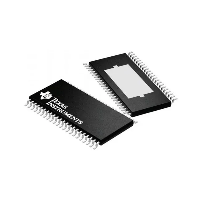
The 44-pin TSSOP footprint is standard, but the exposed-pad layout is non-negotiable — treat the thermal land as a required feature, not an option.
Fault protection and what it covers on the bench
The DRV8312DDWR includes current limiting, over-temperature, short-circuit, and UVLO fault protection. The UVLO monitors the 12 V logic supply — if it dips below the threshold, the outputs are disabled cleanly, preventing the FETs from operating in the linear region and overheating. The short-circuit protection acts cycle-by-cycle, limiting the peak current before the 6.5 A rating is exceeded. The status flag output signals a fault condition to the host controller, allowing the system to log the event or initiate a safe shutdown. This is a single-wire open-drain output — pull it up to the logic supply voltage through a 10 kOhm resistor.