Sensing range and bandwidth — what they mean for the measurement
The DRV5053OAQDBZRQ1: The ±73 mT sensing range defines the linear region where the analog output voltage is proportional to the applied magnetic field. Outside this range the output saturates — the measurement is no longer linear. For a current-sense application using a busbar with a known magnetic gain (mT/A), this sets the maximum measurable current before the sensor clips. The 20 kHz bandwidth means the sensor can track magnetic field changes up to that frequency. In a motor-drive PWM loop switching at 8–16 kHz, the sensor passes the fundamental and lower harmonics — the output settles within one switching cycle. For position sensing in a fast linear actuator, the bandwidth determines the maximum edge rate the sensor can follow without phase lag.
Automotive temperature grade and AEC-Q100 qualification
The AEC-Q100 qualification means it has passed the reliability stress tests (preconditioning, temperature cycling, HAST, high-temperature operating life) required for Tier-1 automotive PPAP submissions. The temperature-compensated feature reduces the sensitivity drift across the operating range.
Supply voltage and output type — integration into the signal chain
The 2.7 V to 38 V supply range lets the sensor run directly off an unregulated 12 V automotive battery (which dips to 4.5 V during cold crank and rises to 16 V during load dump) or a 24 V industrial bus. The analog voltage output (0 V to Vcc proportional to field) connects directly to an ADC input on the downstream MCU or DSP. There is no digital interface to configure — the output is ready at power-up after the 20 kHz bandwidth settling time. The 2.3 mA max output current means the sensor can drive a moderate capacitive load on the ADC input without an external buffer.
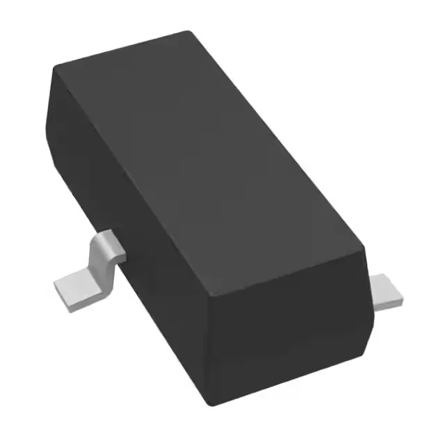
The SOT-23-3 package (TO-236-3, SC-59 equivalent) is a three-pin surface-mount footprint common across the DRV5053 family. The pinout is standard: Vcc, GND, and analog output. No exposed thermal pad — the junction-to-ambient thermal resistance is set by the copper area on the PCB. The 3.6 mA max supply current produces negligible self-heating, so no special thermal management is needed.