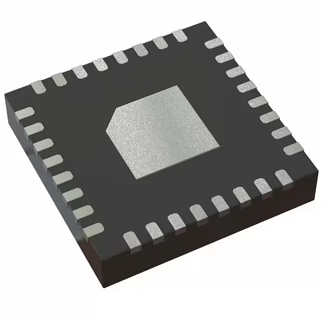
Active clock fanout with 3.5 GHz ceiling
The CDCLVP111RHBR: The 1:10 ratio means a single reference clock fans out to ten destinations on the board, saving a cascade of lower-fanout buffers. Differential signaling all the way through (input and output) keeps common-mode noise rejection intact, which matters when the clock trace runs across a mixed-signal PCB with switching regulators nearby.
Supply and temperature range for system fit
The pad is the only thermal path — no airflow over the package helps much without that PCB thermal relief.