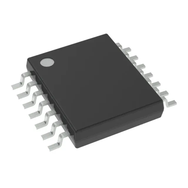
230 MHz spread-spectrum clock synthesis in a 14-TSSOP
The Texas Instruments CDCE913PWR is a programmable PLL-based VCXO clock synthesizer configured as a spread-spectrum clock driver. It accepts either an LVCMOS reference or a crystal input and delivers up to three LVCMOS clock outputs from a single PLL core, with independent divider and multiplier stages per output path. The maximum output frequency reaches 230 MHz, making it a fit for PCIe reference clocks, Ethernet PHY timing, and FPGA fabric clocks that need EMI reduction through spread-spectrum modulation.
Supply rail flexibility and temperature range
This split-rail architecture lets the PLL core run at a lower voltage for reduced power while the output buffers swing at the logic level required by the downstream load — 3.3 V for legacy ASIC interfaces or 2.5 V for lower-power FPGA banks.
No last-time-buy window, no NRND flag, and no successor part number has been issued. For BOM planning, it means the line is stable for new designs and there is no supply discontinuity to hedge against with a second-source qualification.
14-TSSOP footprint and RoHS compliance
The suffix PWR denotes the tape-and-reel shipping format. It is ROHS3 compliant, with no exemptions that complicate end-product environmental declarations for EU or California markets.
Spread-spectrum modulation — the EMI angle
The spread-spectrum feature modulates the PLL output frequency around the center frequency, reducing peak radiated emissions at the fundamental and harmonic frequencies. This is the primary reason to pick this part over a fixed-frequency PLL clock buffer: it can push a design through FCC or CISPR Class B pre-compliance without adding ferrite beads or shielding cans on the clock traces. The modulation profile is programmable through the device's serial interface, so the spread amount and modulation rate can be tuned to the system's jitter budget.