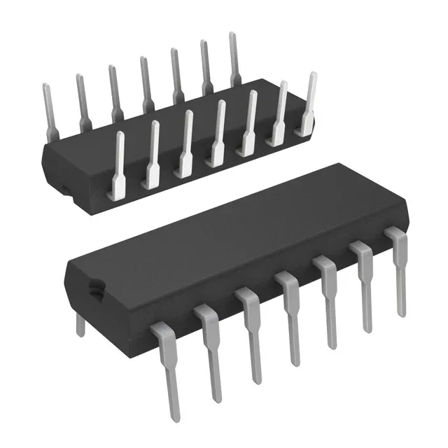
Texas Instruments CD74HCU04E — Interface & Transceivers

Texas Instruments CD74HCU04E 74HCU Hex Inverter, 2V-6V

MPNCD74HCU04E
End of Life

Texas Instruments 74HCU series hex inverter, CD74HCU04E, 6-circuit, 2V-6V supply, through-hole 14-DIP (0.300", 7.62mm), -55°C to 125°C, ROHS3 compliant.

$0.62Ref. price · indicative, final on quote
Packaging14-DIP (0.300", 7.62mm)
RoHSROHS3 Compliant
Series74HCU
Independent supplier — new & surplus stockAuthenticity-screened · ESD-safe packingListing updated Aug 2026

Specifications

CD74HCU04E specifications
ParameterValue
Series74HCU
Logic typeInverter
MountingThrough Hole
Voltage2V ~ 6V
Current - quiescent2 µA
Current - output high, low5.2mA, 5.2mA
I/O channels1
Operating temperature-55°C ~ 125°C
PackageTube
Case14-DIP (0.300\", 7.62mm)
Number of circuits6
Input logic level - low0.3V ~ 1.1V
Input logic level - high1.7V ~ 4.8V
Max propagation delay @ v, max CL12ns @ 6V, 50pF

Product details

12 ns propagation delay at 6 V — the speed floor for the 74HCU unbuffered inverter

The CD74HCU04E is a hex unbuffered inverter from TI's 74HCU series, packing six independent inverter gates in a single 14-pin DIP. Each gate accepts a single input and inverts it, with propagation delay rated at 12 ns max into a 50 pF load at 6 V supply — this sets the maximum toggle rate the downstream logic sees before the output edge degrades. The input logic thresholds scale with VCC: low-level threshold is 0.3 V to 1.1 V, high-level 1.7 V to 4.8 V, so the gate switches cleanly across the full supply range.

Wide temperature range and low quiescent draw suit industrial and remote hardware

Quiescent current draws just 2 µA max, so the gate adds negligible standby drain in battery-backed or energy-harvesting designs. Each output sources or sinks 5.2 mA, enough to drive one standard LSTTL load or a low-power LED indicator. For heavier fan-out, buffer the output with a discrete transistor or a dedicated line driver.

Through-hole 14-DIP package — breadboard and legacy board fit

Housed in a 14-lead plastic DIP (0.300-inch row spacing, 7.62 mm body width), the CD74HCU04E mounts through-hole and fits standard 0.100-inch pitch prototyping boards. The 14-PDIP supplier package code confirms the leadframe and mold compound are the same as the generic 14-DIP outline — no footprint surprise when laying out a new board or replacing a pulled part. Delivered in tube packaging, so the leads stay co-planar through shipping and the part feeds directly into a manual insertion station or a tube-fed auto-insertion machine without re-reeling.

Frequently asked questions

What is the propagation delay and what does it mean for my timing budget?

Maximum propagation delay is 12 ns at 6 V supply into a 50 pF load. This means the output transition finishes within 12 ns of the input edge under those conditions. At lower supply voltages (e.g., 2 V) the delay increases; budget 20–25 ns at 3.3 V for a safe timing closure if the datasheet derating curve is not available.

What compliance documentation does Texas Instruments provide for CD74HCU04E?

Texas Instruments provides ROHS3 compliance certification. No separate UL, IEC, or REACH documentation is listed in the standard product data, but the ROHS3 declaration is included with the shipment documentation. For specific regulatory filings, request the TI environmental compliance report at RFQ time.