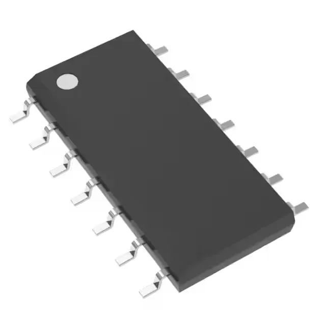
Texas Instruments CD74HCT74M96 — Discrete Semiconductors

CD74HCT74M96 D-Type Flip-Flop, 50 MHz, 14-SOIC

MPNCD74HCT74M96
End of Life

Texas Instruments 74HCT series D-type flip-flop, CD74HCT74M96, dual 1-bit, positive edge trigger, complementary output, 14-SOIC, 50 MHz clock, 4.5-5.5 V supply.

$0.63Ref. price · indicative, final on quote
Packaging14-SOIC (0.154", 3.90mm Width)
RoHSROHS3 Compliant
Series74HCT
Independent supplier — new & surplus stockAuthenticity-screened · ESD-safe packingListing updated Aug 2026

Specifications

CD74HCT74M96 specifications
ParameterValue
TypeD-Type
Series74HCT
Output typeComplementary
Trigger typePositive Edge
MountingSurface Mount
Supply voltage4.5V ~ 5.5V
Current - quiescent4 µA
Current - output high, low4mA, 4mA
Clock frequency50 MHz
Operating temperature-55°C ~ 125°C (TA)
PackageTape & Reel (TR); Cut Tape (CT)
FunctionSet(Preset) and Reset
Case14-SOIC (0.154\", 3.90mm Width)
Input capacitance10 pF
Number of elements2
Number of bits per element1
Max propagation delay @ v, max CL35ns @ 4.5V, 50pF

Product details

What this flip-flop does on the board

The CD74HCT74M96 is a dual D-type flip-flop from the 74HCT family, each with independent Set (Preset) and Reset inputs. It toggles the complementary outputs on the positive edge of the clock — the 50 MHz max clock frequency sets the data-rate ceiling for the bus or register it drives. The 35 ns propagation delay at 4.5 V with 50 pF load means the output settles within one clock cycle at 28 MHz — the timing budget for the downstream logic includes this delay plus the input setup time.

A board in an engine-bay ECU or an outdoor base station that sees 105°C on a summer day has margin to the upper limit. The 10 pF input capacitance is typical for HCT inputs — the clock line driver must source enough current to charge this capacitance at 50 MHz without edge degradation. Output drive is 4 mA source and sink at the rated supply — sufficient for driving a single TTL load or a short PCB trace. For fan-out beyond two loads, a buffer stage is needed to keep the rise time within the downstream logic's input threshold window.