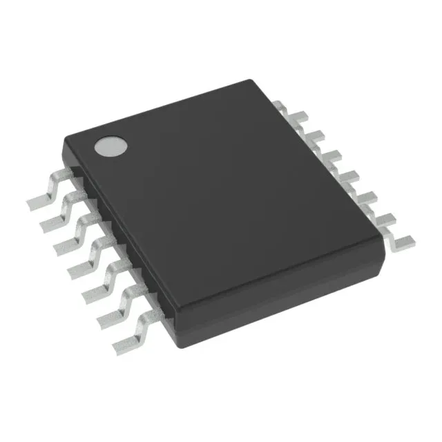
Schmitt-trigger hex inverter for noise-prone 5 V logic rails
The CD74HCT14PWR is a Texas Instruments 74HCT-series hex inverter with Schmitt-trigger inputs on all six channels. Each inverter accepts one input and outputs the inverted logic level, with the Schmitt-trigger hysteresis cleaning up slow or noisy edges on the input signal. The Schmitt-trigger thresholds — 0.5 V to 0.6 V low, 1.9 V to 2.1 V high — provide a clean transition window that rejects noise between the levels.
14-TSSOP footprint and PCB integration
The 14-TSSOP footprint is common across the 74HCT logic family, so a single PCB land pattern serves multiple logic functions if the BOM changes. Quiescent current is a maximum of 2 µA, so the device adds negligible standby draw in battery-backed or always-on systems. Output drive capability is 4 mA source and 4 mA sink at the rated supply voltage — sufficient for driving the input of a following CMOS or TTL gate, an LED indicator through a series resistor, or a short PCB trace. For loads exceeding 4 mA, a buffer stage is needed.
Propagation delay and timing budget
The maximum propagation delay is 38 ns at 4.5 V with a 50 pF load. This sets the upper bound on the data rate through the inverter chain — for a clock or data signal, the combined delay of multiple series stages must stay within one clock period to avoid setup-time violations at the receiving flip-flop. Because the delay is specified at 4.5 V (the lower end of the supply range), the actual delay at 5.0 V will be slightly shorter. The 50 pF load capacitance is typical of a short PCB trace plus one or two gate inputs; heavier fan-out increases the delay proportionally.
Active production and compliance status
Texas Instruments lists this under the 74HCT series, a well-established logic family with broad second-source availability. The 14-TSSOP package is a standard industry footprint, so alternative suppliers offering the same function in the same package can be cross-referenced if supply tightens.