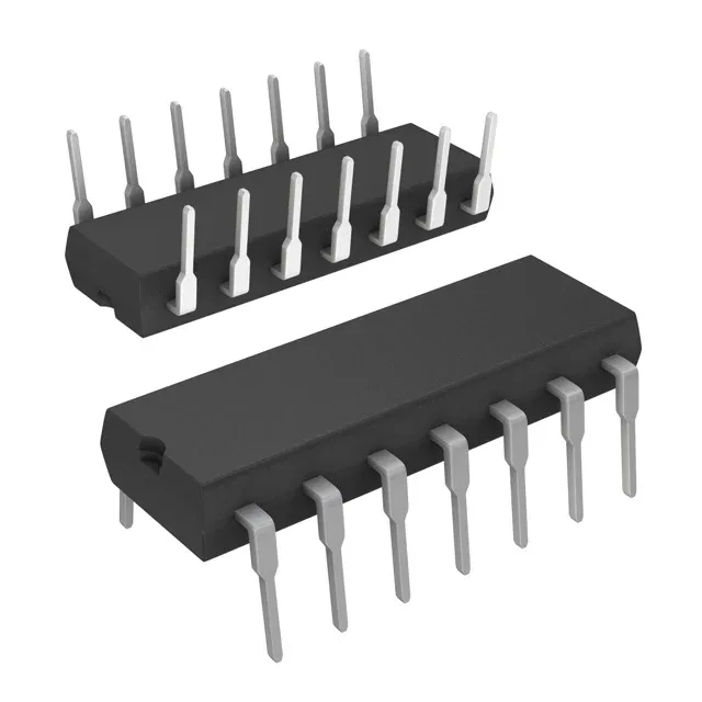
Hex inverter on a 5V rail — what the ratings mean for your BOM
The CD74HCT04E packs six independent inverter gates into a single 14-pin DIP, each gate taking one input and delivering the inverted output. Supply voltage runs from 4.5 V to 5.5 V, so it sits directly on a 5 V logic rail without a separate regulator. Input thresholds are TTL-compatible: a low below 0.8 V and a high above 2 V. That means it can be driven directly by 5 V TTL outputs or by 3.3 V logic with a pull-up — no level translator needed as long as the high-side meets 2 V. Propagation delay is 19 ns typical at 4.5 V into a 50 pF load. For a 5 V system clocking at 25 MHz, that delay adds about half a period of skew per gate — budget it into your timing closure if the signal passes through multiple inverters in series.
Temperature range and deployment context
Rated for -55°C to 125°C operating ambient, this part covers the full industrial and military temperature envelope. An engine-bay ECU or a downhole sensor interface that sees 105°C on the board still has margin before the die hits the upper limit. The 14-DIP through-hole package (0.300" body width, 7.62 mm pitch) is a breadboard- and protoboard-friendly footprint. It also survives hand-solder rework cycles without the pad-lift risk of a fine-pitch SMD part — useful for low-volume or field-repairable assemblies.
Output drive and quiescent current
Each output can sink or source 4 mA — the standard fan-out for the HCT family. That drives one or two standard TTL loads or a CMOS input on the same 5 V rail, but it won't directly switch a relay coil or LED without a buffer transistor. Quiescent current maxes at 2 µA across the full supply range. In a battery-backed system that keeps the logic powered during sleep, the inverter's own draw is negligible — the leakage of the upstream pull-up resistors will dominate the standby budget.
Lifecycle and sourcing posture
The 74HCT family has been in continuous production for decades, and TI shows no sign of winding it down. ROHS3 compliant per the L* entry, so it ships with Pb-free solder terminations.