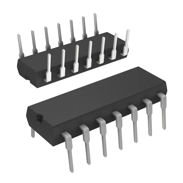
Hex inverter with Schmitt-trigger inputs
The CD74ACT14E: Each channel inverts a single input, and the Schmitt-trigger action at the input (low threshold 0.8 V to 1.3 V, high threshold 1.4 V to 2.0 V) cleans up noisy or slow edges before the logic stage sees them. The 24 mA symmetric output drive (both source and sink) handles standard fan-out to multiple loads without external buffers.
The part suits avionics, satellite, downhole instrumentation, or any environment where the ambient temperature swings beyond the commercial or industrial band. The 14-DIP package (0.300-inch body width, 7.62 mm) is a through-hole footprint that survives high-vibration and repeated thermal cycling better than a surface-mount equivalent in the same temperature range. Hand-solderable for prototype runs, wave-solderable for production.
Propagation delay and timing margin
Maximum propagation delay is 14.5 ns at 5 V with a 50 pF load. This sets the data-rate ceiling — the output rise time into the load capacitance adds to this figure, so the actual toggle rate at the receiver is lower than the bare 14.5 ns suggests. Budget this into your timing closure for clocked paths. Quiescent current is 4 µA max, negligible for the power budget in a mixed-signal board where the logic section draws milliamps per gate when switching.
Sourced to order against BOM quantities through independent distribution.