The I²C interface gives the host microcontroller control over charge current, timer, and voltage settings, along with fault protection for overcurrent and overvoltage conditions.
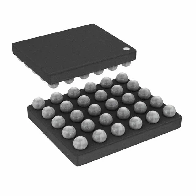
The 30-DSBGA package (0.4 mm pitch typical for this family) demands careful PCB layout: a solid thermal via pattern under the package is needed to pull heat away from the die during a full 1.5 A charge cycle. The land pattern follows the standard DSBGA footprint; stencil aperture design for the solder balls is critical to avoid head-in-pillow defects in reflow.
Programming charge parameters over I²C
The I²C bus is the only control interface — no standalone pin-strap resistors for current setting. The host writes to registers to set the charge current (programmable up to 1.5 A), charge timer, and target battery voltage (max 4.52 V). This makes the BQ25618YFFT a good fit for designs where the system microcontroller already manages the PMIC bus and can adjust the charge profile in firmware for different battery chemistries or capacities. The overcurrent and overvoltage fault protection are hardware-enforced, independent of the I²C communication state.