500 mA programmable charge current — the BOM-fit ceiling
The BQ25155YFPT is a single-cell linear charger with a 500 mA maximum charge current. That is the hard ceiling — the actual charge rate is set via I²C registers, so the same PCB can serve a 100 mA earbud cradle and a 450 mA wearable dock by changing the firmware, not the resistor divider. Battery regulation voltage tops out at 4.6 V, which covers standard Li-ion (4.2 V) and Li-Poly (4.35 V) cells, plus LiFePO4 at lower termination voltages — the I²C registers select the target per chemistry.
Input rail and protection envelope
Maximum supply voltage is 5.25 V — a standard USB VBUS at 5.0 V nominal sits inside the window, but a hot-plug transient or a 5.25 V adapter rail is the abs-max. The integrated fault protection covers over-current, over-temperature, over-voltage, and short-circuit on the output, so the charge path is self-protecting against a failed cell or a miswired pack. A portable medical monitor or a handheld scanner that sees a hot dashboard in summer stays within the junction rating.
20-bump DSBGA — board integration note
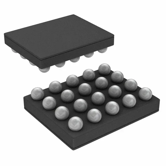
The part is housed in a 20-bump DSBGA — 0.4 mm pitch, no exposed thermal pad. The PCB must support fine-line fan-out between bumps; a four-layer stack-up with microvias is typical for the escape routing. The stencil aperture for each bump should match the TI recommended land pattern in the datasheet to avoid solder bridging. Cut Tape works for prototyping or low-volume builds.