1.5 A charge current, I²C programmability — what drives the fit
The BQ24270RGER: Maximum charge current of 1.5 A sets the charge-rate ceiling for a single-cell Li-Ion pack. For a 2000 mAh cell, that is a 0.75 C rate — fast enough for a consumer device charge cycle without pushing the cell into its thermal limit. The I²C interface means the charge current, termination threshold, and input current limit are set in software rather than by fixed resistor dividers — useful when a single PCB layout must serve multiple battery capacities across SKUs. Supply voltage max of 6 V covers USB VBUS (5 V nominal) with margin for the cable drop and connector transients. The input over-voltage protection clamps the FET before the 6 V ceiling is exceeded.
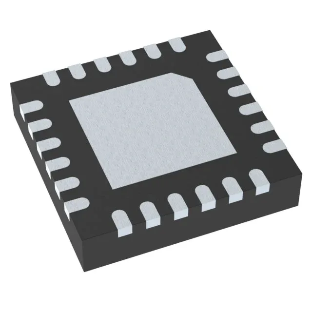
Fault protection includes over-temperature, over-voltage, and short-circuit. The over-temperature loop reduces charge current when the die hits the thermal regulation threshold, so a hot board in a sealed enclosure throttles down rather than tripping the input fuse. The 24-VQFN package with exposed pad requires a thermal via array under the paddle to pull heat into the PCB ground plane. Without adequate thermal vias, the 1.5 A charge current will push the die into current foldback on a 2-layer board.
Single-cell Li-Ion — the chemistry and cell count
Designed for single-cell Lithium-Ion packs with a nominal battery voltage of 3.7 V. The charge algorithm is constant-current / constant-voltage — the I²C-programmed current tapers as the cell reaches 4.2 V regulation. The 3.7 V battery pack voltage is the nominal mid-point — the charger regulates the float voltage to 4.2 V, which is the standard termination for Li-ion cells with a graphite anode.