It uses an I²C interface to program the charge current, so the host MCU can adjust the rate without swapping a set-resistor — useful when the same board must charge from USB, a 5 V wall adapter, or a 9 V supply.
Why the 2 A ceiling and 10.5 V input matter on the BOM
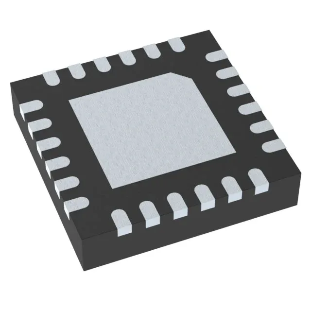
The 2 A max charge current sets the thermal budget for the 24-VQFN (4x4 mm) exposed-pad package. The 10.5 V input ceiling covers 5 V USB and 9 V quick-charge adapters but not 12 V rails — a 12 V input exceeds the abs-max and kills the part on first plug-in. Fault protection is on-die: over-current, over-temperature, and over-voltage shut down the pass FET without an external fuse or supervisor. That saves a PTC and a comparator on the BOM — worth factoring into the board-area budget.