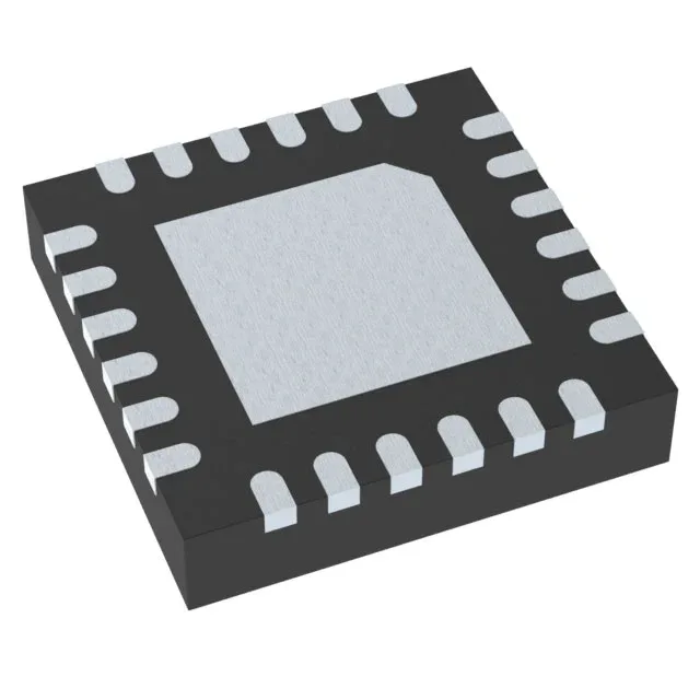
It accepts a supply up to 10.5 V and delivers a programmable constant charge current up to 2 A to a 4.2 V battery pack. The I²C interface lets a host microcontroller set the charge current, monitor status, and enable fault handling — a step up from pin-strapped standalone chargers. Over-temperature and over-voltage protection are integrated, so the BOM stays lean for portable equipment, IoT endpoints, and handheld instruments that run on a single Li-ion cell.
The maximum supply voltage is 10.5 V, which covers standard 5 V USB bus-powered designs and 9 V wall adapters, but not 12 V or higher rails. If your system runs from a 12 V intermediate bus, you need a front-end regulator or a different charger rated for that input. The I²C interface means the host can read the charger's status and adjust the current limit on the fly — useful for thermal throttling or for matching the charge rate to the adapter's capability.
2 A charge current and the thermal budget
The constant-current charge phase is programmable, so a design can back off to 1 A or 500 mA if the PCB area is tight or the ambient runs warm. The single-cell chemistry is Li-Ion only; this part does not support LiFePO4 or higher-cell-count packs.
Active lifecycle, no near-term obsolescence risk
ROHS3 compliant. For a production BOM this means no last-time-buy pressure and no forced redesign in the near term. If you are qualifying this for a new design, the active status and I²C flexibility make it a safe selection for medium-volume portable products.