Shunt reference for precision feedback and biasing
Its ±1% tolerance gives you a tight output window without trimming, and the 80 µA minimum cathode current lets it operate in low-power bias chains where every microamp counts. The output is adjustable from 2.5 V up to 36 V, covering the common 3.3 V, 5 V, 12 V, and 24 V rails you see in industrial power supplies, automotive ECUs, and isolated converter secondary-side regulation.
125°C junction — under-hood and industrial environments
The 125°C junction rating means the reference holds its accuracy through thermal cycling without derating the output current. If your design lives in a heated enclosure or near a motor drive, this temperature grade saves you from having to add active cooling or overspec the bias resistor.
15 mA output — resistor sizing and dissipation
The 15 mA output current is the maximum the shunt can sink while maintaining regulation. In practice, you size the bias resistor so the cathode current stays above the 80 µA minimum under all load conditions, and below 15 mA at maximum input voltage. For a 24 V rail dropping to 5 V output, a 1.3 kΩ resistor biased at roughly 15 mA works, but check the power dissipation in the resistor — at 24 V input the resistor drops 19 V at 15 mA, which is 285 mW. Use a 0.5 W or larger resistor if your input sits at the upper end of the range.
4-X2SON (1x1 mm) — layout and assembly notes
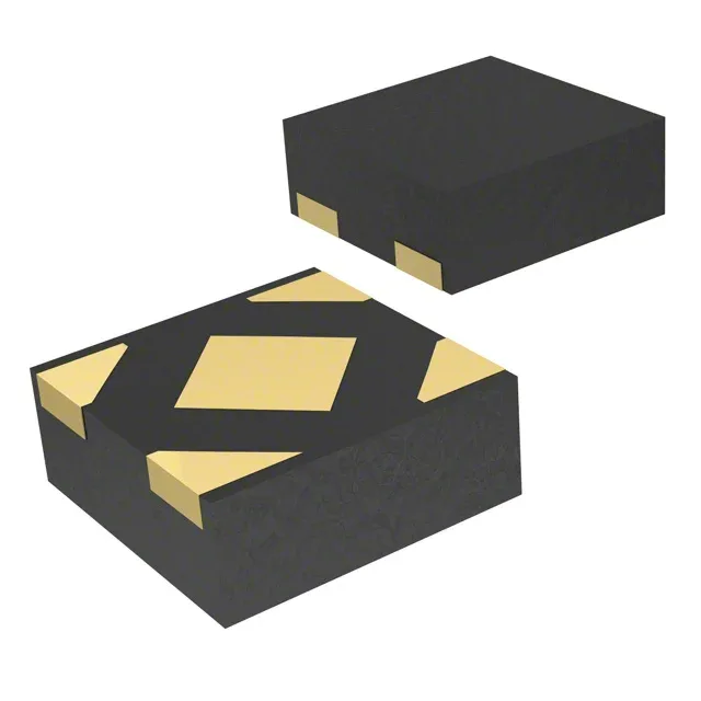
The 4-XDFN exposed pad package, also called 4-X2SON, measures just 1x1 mm — smaller than a 0402 resistor. That saves board area in dense layouts like USB-C chargers, LED drivers, or sensor modules, but the tiny footprint demands careful solder paste stencil design and a reflow profile that matches the exposed pad. The pad is the thermal path for the die; make sure your PCB has a via-in-pad or a short trace to a copper plane to keep junction temperature in check when the part is sinking close to 15 mA continuously.
For dual-sourcing or a pin-compatible second source, the LM4132AMF-4.1/NOPB is a series reference with tighter tolerance (±0.05%) but a fixed 4.096 V output — functionally different topology (series vs. shunt), so evaluate your bias network before substituting.