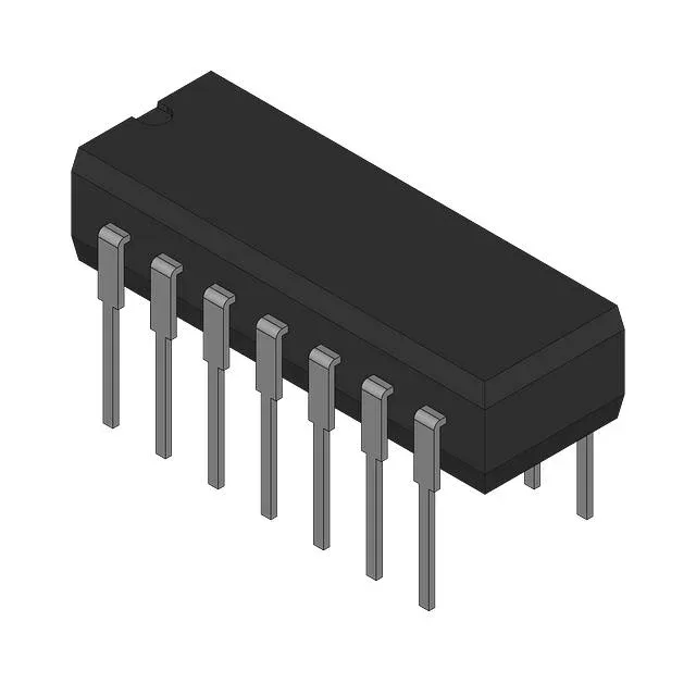
Triple 3-input NAND in a hermetic ceramic DIP
The 74S10DC is a 74S-series triple 3-input NAND gate from Texas Instruments, packaged in a 14-lead ceramic DIP (CDIP) with 0.300-inch body width. It performs the NAND logic function across three independent gates, each with three inputs — a configuration used in address decoding, gating, and combinatorial logic where the third input eliminates the need for an external inverter on a two-input gate.
5 ns propagation delay at 5 V — the speed ceiling for the logic path
Maximum propagation delay is 5 ns at 5 V supply with a 50 pF load. This sets the timing budget for the signal path: the 5 ns figure is the worst-case delay from any input transition to the output crossing the threshold, so the downstream latch or register must hold its data window open long enough to absorb this delay plus the interconnect and input capacitance of the receiving device.
14-CDIP hermetic package — through-hole board integration
The 14-CDIP (0.300-inch, 7.62 mm) ceramic dual-inline package with through-hole leads is designed for socketed or soldered insertion into a PCB. The ceramic body provides a hermetic seal — moisture ingress is negligible compared to plastic DIPs, so the part has no MSL floor-life constraint and does not require a moisture bake before wave or hand soldering. The 0.100-inch (2.54 mm) lead pitch is standard for DIP layouts; the 0.300-inch row spacing fits the narrower DIP footprint (not the 0.600-inch wide-body).