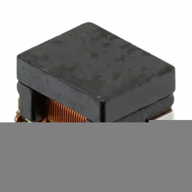
Active production, AEC-Q200 qualified
The ACT1210-101-2P-TL00: AEC-Q200 qualification means the choke passed the passive-component stress tests for automotive-grade reliability: thermal shock, moisture resistance, vibration, and solder heat.
What the ratings mean for the BOM line
This is a 2-line common mode choke — the two windings share a common magnetic core, so common-mode noise sees high impedance while differential signal current cancels the flux. The 5.1 kOhms impedance at 10 MHz is the peak suppression band for conducted emissions in the 1–30 MHz range, typical for automotive CAN bus, LIN bus, or low-speed sensor lines. The 1.5 Ohm max DCR means the choke drops 0.225 V at full rated current; for a 5 V logic rail that is 4.5% loss, acceptable for most signal lines but worth checking if the downstream IC has a tight supply tolerance. Inductance is 100 µH at 100 kHz — this is the common-mode inductance per winding. The choke's effective filtering bandwidth extends from the resonant frequency of the inductance with the parasitic capacitance, typically a few MHz up to the self-resonant frequency. Below 100 kHz the impedance is inductive; above 10 MHz it transitions to capacitive.
Package and board-fit
The four pads are two input and two output — the winding direction is marked on the body. Surface mount, reflow-solder compatible. The 2.50 mm height is a constraint for low-profile enclosures; check clearance above the tallest nearby component.