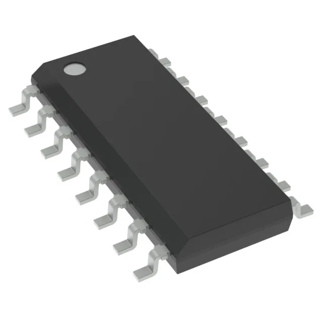
What the 800 V breakdown and 10 W rating mean for your offline supply
The VIPER17LD integrates an 800 V avalanche-rugged MOSFET and a PWM controller in a single 16-SOIC package, targeting isolated flyback converters up to 10 W. The 800 V breakdown gives 200 V of margin above a typical 600 V bulk rail after reflected voltage and leakage spike — enough to avoid derating headaches in universal-input (85–265 VAC) designs. The 10 W power ceiling is tied to the SO-8 footprint's thermal impedance; a 4-layer board with a copper pour under the exposed pad pulls the junction temperature down at full load.
Switching frequency, duty cycle, and startup behaviour
Fixed 60 kHz switching frequency with a 70% maximum duty cycle — the 60 kHz keeps the transformer core size small while staying below the AM band for conducted emissions. The 14 V startup threshold and 8.5 V to 23.5 V Vcc range mean the IC starts cleanly from a bulk cap voltage and stays alive through the auxiliary winding once the converter is running. Fault protection includes current limiting, over-temperature, and over-voltage on the Vcc pin — the OVP latches off the gate drive if the auxiliary winding overcharges the supply rail.
For volume pricing and lead time, submit an RFQ against your BOM quantity — the part is sourced to order through our distribution channel.
Design-in checklist for the 16-SOIC package
The 16-SOIC (0.154-inch width, 3.90 mm body) has an exposed paddle on the bottom — the datasheet recommends a thermal land on the PCB with at least 4 vias to a ground plane. The paddle is the drain node at 800 V, so the copper area must be sized for both thermal dissipation and creepage clearance to low-voltage pins.