48% duty cycle — flyback and boost topology fit
Its maximum duty cycle of 48% is a hard limit — the controller cannot exceed this, which suits single-switch flyback designs where the duty cycle stays below 50% to avoid transformer saturation. Designers migrating from a 50%+ duty cycle part will need to re-evaluate the transformer turns ratio or switch to a different controller.
Switching frequency up to 500 kHz — transformer sizing trade-off
The oscillator runs up to 500 kHz, allowing smaller magnetic components compared to lower-frequency controllers. At the upper end, switching losses in the MOSFET and core losses in the transformer increase, so the actual frequency choice is a trade-off between size and thermal budget. The part does not include clock sync, so multiple converters on the same board must be designed with beat-frequency management in mind.
Supply range 10V to 30V — bias rail compatibility
The Vcc supply range of 10V to 30V covers common bias rails from 12V to 24V auxiliary windings. The undervoltage lockout thresholds are set internally for the UC3844 variant, so the 10V minimum ensures reliable startup from a 12V rail. If the design uses a 9V bias, a different UC384x variant with lower UVLO thresholds is needed.
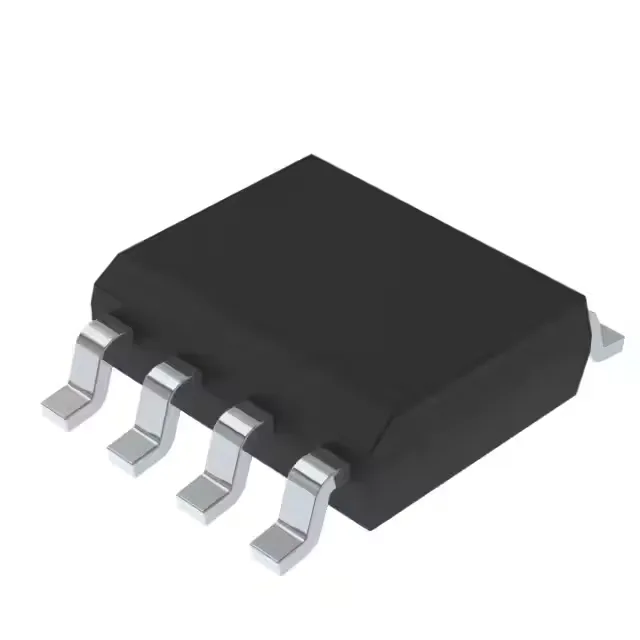
8-SOIC package — footprint and thermal considerations
The narrow body limits power dissipation — the copper area on the PCB under the package sets the effective thermal resistance. For designs pushing the switching frequency or operating near the supply maximum, ensure adequate copper pour and vias to the ground plane.