Active production — sourcing for your BOM line
That gives procurement a stable supply horizon for production builds. It is ROHS3 compliant, clearing the restriction-of-hazardous-substances gate for EU and most global markets.
Boost and flyback controller — key switching specs
This is a single-output, current-mode PWM controller built for boost and flyback topologies. The 96% maximum duty cycle lets it maintain regulation across a wide input-to-output voltage ratio, which matters for designs like an offline flyback where the primary-to-secondary turns ratio demands a long on-time. Switching frequency goes up to 500 kHz. That is high enough to shrink the magnetic component (transformer or boost inductor) to a small surface-mount part, but the trade-off is higher switching loss in the external MOSFET — the designer should budget gate-drive power accordingly. Supply voltage range is 7.6 V to 30 V on the Vcc pin. That 7.6 V minimum means the chip needs a bias rail above the undervoltage-lockout threshold before it starts switching — a common startup resistor and auxiliary winding arrangement handles it in a flyback.
Temperature grade sets the application boundary
This is a commercial-grade part — fine for an indoor power supply, a telecom adapter, or a white-goods control board. It will not meet the -40°C requirement of an automotive or outdoor industrial design. Reflow profile is the usual lead-free SOIC profile; the part has no exposed pad, so the die heat flows through the leads and into the copper traces — a short, wide trace from pin 5 (ground) helps pull heat away.
Rework note — 8-SOIC is a clean lift
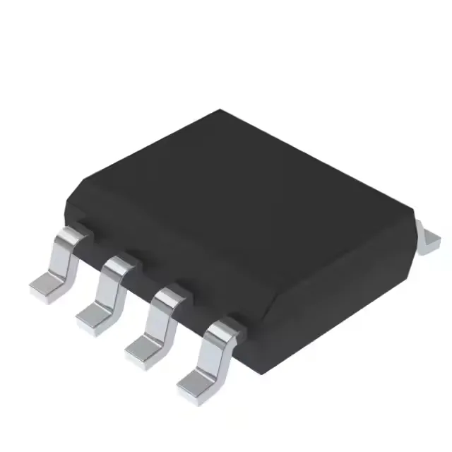
The 8-SOIC package is one of the easiest to rework by hand. The 0.154-inch (3.90 mm) body width means the leads are spaced wide enough to flood with solder wick without bridging. Because the part lacks a thermal pad underneath, there is no risk of hidden voids or cold joints under the body. A standard hot-air nozzle at 300°C with a 3-second dwell lifts the part cleanly — just work the wick across each side and the pads come up flat.