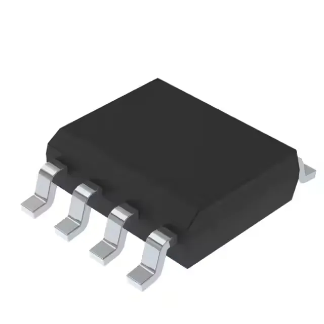
The UC3842BD1013TR is a current-mode PWM controller from STMicroelectronics, built around the industry-standard UC3842 architecture. It targets offline and DC-DC converters in boost and flyback topologies, with a switching frequency rated up to 500kHz. That ceiling lets the designer shrink the magnetic component — a 500kHz flyback transformer is roughly one-quarter the volume of a 100kHz design — but the trade-off is tighter layout discipline to keep the sense resistor and current-sense loop free of noise.
96% duty cycle — the step-up headroom
Maximum duty cycle is 96%. In a boost converter that means the output can be up to 24 times the input voltage at light load, ignoring parasitics. In a flyback, the high duty cycle gives the primary winding more time to store energy per cycle, which helps maintain regulation across a wide input-voltage range. The practical limit is the minimum off-time needed to reset the transformer core — the 4% off-time at 500kHz is 80 ns, which demands a fast-recovery clamp on the primary.
Supply voltage and bias strategy
The Vcc range is 10V to 30V. That is higher than a typical 5V or 12V auxiliary rail — the controller must be biased from the converter's own output or a dedicated winding, not from a pre-regulated low-voltage bus. The undervoltage lockout (UVLO) thresholds are set internally for the UC3842 family: the turn-on threshold is 16V, the turn-off is 10V, so the bias supply needs to deliver at least 16V during startup before the converter self-supplies.
This is a commercial-grade part — it belongs in benchtop power supplies, telecom indoor rectifiers, and appliance power stages. Not rated for the -40°C cold crank of an automotive environment or the 85°C ambient inside a sealed industrial enclosure. If the design lives in a conditioned space, this is the cost-effective choice; if it sees outdoor or under-hood temperatures, step up to the industrial-temperature variant.
Product status is Active. For a BOM that uses this controller, there is no urgency to qualify a second source or stockpile inventory.