What the 15 A RMS rating means for your load
The TN1515-600B-TR is a standard-recovery SCR rated for 15 A RMS on-state current and 9.5 A average — this is the continuous conduction limit at the case temperature derating curve, not a peak pulse number. For a resistive heater or a phase-controlled motor drive, the RMS figure governs the thermal design; the average matters when the conduction angle is narrow and the current waveform is highly non-sinusoidal. Its 600 V off-state blocking voltage covers the typical single-phase 230 VAC line (peak ~325 V) with healthy margin, and it also handles 400 VAC three-phase line-to-neutral peaks (~565 V) if the transient voltage clamping is adequate. The 150 A / 165 A non-repetitive surge current (50/60 Hz) means it can survive a short-circuit event long enough for an upstream fuse or breaker to clear — budget the I²t of the protection device against the SCR's surge capability.
Gate drive and holding current — sizing the trigger circuit
Maximum gate trigger current is 15 mA at 1.3 V gate voltage — a standard microcontroller GPIO with a series resistor and a small NPN transistor can drive this directly. The 40 mA holding current means the SCR will stay latched once triggered as long as the load current stays above that threshold; below 40 mA the device turns off, which is useful for half-wave or phase-angle circuits where you want natural commutation near the zero crossing. Off-state leakage is 5 µA maximum at rated voltage — negligible for most designs, but in a high-impedance gate-drive circuit (like a capacitive discharge ignition) that leakage can charge the gate capacitance and cause unintended turn-on if the gate is left floating. Tie the gate to cathode through a resistor (typically 1 kΩ) when the drive is inactive.
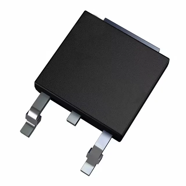
Package and board integration — DPAK (TO-252)
The device is RoHS3 compliant and supplied in Tape & Reel (TR) or Cut Tape (CT) options for pick-and-place assembly.