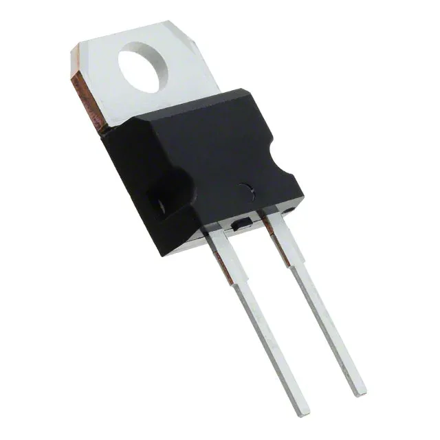
105 ns trr — the spec that keeps the boost stage cool
That trr figure is what separates this from a standard 50/60 Hz rectifier — it's sized for the hard-switching node of a PFC boost, a flyback clamp, or a motor-drive freewheel path where the diode's turn-off loss directly heats the heatsink. The TO-220AC package (TO-220-2 outline) keeps the thermal path through the tab straightforward for a clip or screw mount.
Forward drop at full load
Maximum forward voltage is 1.3 V at 8 A, which at full rated current puts conduction loss near 10.4 W before switching losses are added. At lighter loads the Vf drops, so average dissipation in a discontinuous-mode PFC is lower than the 8 A continuous figure suggests.
Leakage at rated voltage
It does confirm the die quality — a leaky junction at rated voltage would show up here first. The 600 V rating leaves margin for 400 V bus applications (PFC output, inverter DC link) where transients can ring above the nominal rail.