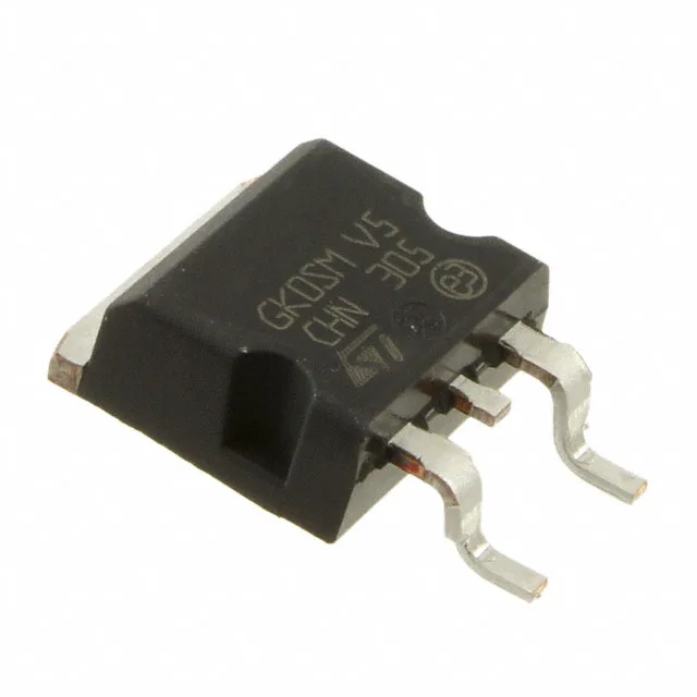
STMicroelectronics STTH30R04G-TR — Discrete Semiconductors

STTH30R04G-TR STMicroelectronics Fast Recovery Diode

MPNSTTH30R04G-TR
Active

STMicroelectronics STTH30R04G-TR, Standard Fast Recovery Diode, 30 A, 400 V, 100 ns trr, Surface Mount D2PAK (TO-263AB), Tape & Reel.

$2.8300Ref. price · indicative, final on quote
PackagingTO-263-3, D²Pak (2 Leads + Tab), TO-263AB
RoHSROHS3 Compliant
Independent supplier — new & surplus stockAuthenticity-screened · ESD-safe packingListing updated Aug 2026

Specifications

STTH30R04G-TR specifications
ParameterValue
Diode typeStandard
MountingSurface Mount
Voltage - DC reverse (Vr)400 V
Voltage - forward (Vf) (Max) @ if1.45 V @ 30 A
Current - reverse leakage @ vr15 µA @ 400 V
Current - average rectified30A
Operating temperature - junction-40°C~175°C
SpeedFast Recovery =< 500ns, > 200mA (Io)
PackageTape & Reel (TR); Cut Tape (CT)
CaseTO-263-3, D²Pak (2 Leads + Tab), TO-263AB
Reverse recovery time100 ns

Product details

30 A fast recovery diode in D2PAK for PFC and boost stages

The STTH30R04G-TR is a 30 A, 400 V fast recovery diode from STMicroelectronics in a surface-mount D2PAK (TO-263AB) package. Its 100 ns reverse recovery time places it in the fast-recovery class, making it suitable for continuous-current-mode PFC stages, boost converters, and output rectification in switching power supplies where reverse-recovery losses matter.

Conduction and switching parametric fit

With a forward voltage of 1.45 V max at 30 A, the conduction loss at full rated current is roughly 43.5 W — the D2PAK's large copper tab on the bottom side is designed to spread that heat into the PCB's copper pour, so the thermal design must budget for the junction-to-ambient path through the board. The 15 µA reverse leakage at 400 V is low enough that standby dissipation in an offline supply stays under 6 mW. The junction temperature range spans -40°C to 175°C, which covers both cold-start in outdoor equipment and the self-heating peak inside a sealed enclosure. The 100 ns trr is specified at typical test conditions — in a hard-switching PFC stage running 50-100 kHz, the recovery charge determines the MOSFET turn-on loss, so the actual switching loss depends on the di/dt and the diode's stored charge, not just the trr number alone.

Frequently asked questions

What is the STTH30R04G-TR's reverse recovery time and why does it matter?

The STTH30R04G-TR has a 100 ns reverse recovery time (trr). This matters because in a hard-switched boost or PFC stage, the diode's recovery charge flows through the MOSFET during turn-on — a faster trr reduces that switching loss and keeps the MOSFET's junction temperature within limits at higher frequencies.

Will the STTH30R04G-TR drop into a board designed for the STTH30R04W?

No — the STTH30R04W is a through-hole device, while the STTH30R04G-TR is surface-mount in a D2PAK package. The pinout and footprint are different, so a board layout change is required.