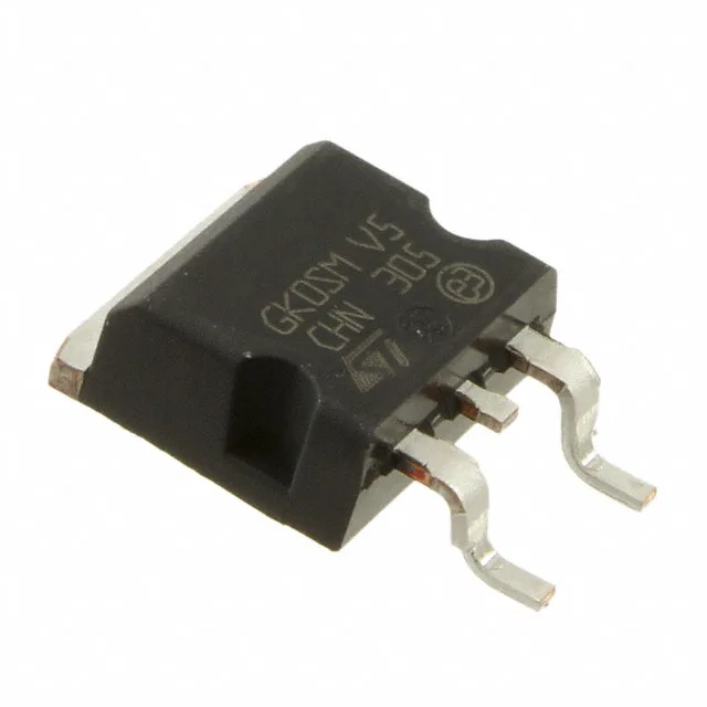
600 V blocking, 30 A average — the power-stage headroom
Its 90 ns reverse recovery time (trr) suits hard-switched topologies in 48 V and 400 V bus converters where recovery losses and EMI need to be contained.
90 ns trr — the switching-speed gate
A 90 ns trr at 600 V blocking places this diode in the fast-recovery class (≤500 ns, >200 mA Io). In a continuous-conduction-mode boost or flyback, the recovery charge directly adds to the switching loss in the companion MOSFET. The 90 ns figure keeps the loss budget manageable at switching frequencies up to roughly 100 kHz; above that a SiC Schottky or a 35 ns ultrafast diode would be the next tier.
175 °C junction — engine-bay thermal margin
The 175 °C ceiling gives about 25 °C more headroom than a standard 150 °C-rated diode, which matters when the PCB copper area is constrained and the thermal impedance from junction to ambient is higher.
D²PAK footprint — thermal pad planning
The pad area and the number of thermal vias to the internal ground plane set the junction-to-board thermal resistance. In a 30 A continuous application, expect the tab to carry the bulk of the heat; the PCB layout engineer should allocate at least 600 mm² of 2 oz copper on the top layer for a 30 A load at 175 °C junction.