85 ns trr — the switching-loss ceiling
Its 85 ns reverse recovery time places it in the ultrafast class for a 600 V, 20 A part — the recovery charge is low enough that a boost PFC or output rectifier stage can run at 100 kHz+ without the diode dominating the switching loss. The 1.55 V forward drop at 15 A is typical for a 600 V planar structure; the trade-off is a slightly higher Vf than a hyperfast silicon diode, but the 85 ns trr keeps the turn-off loss in check.
20 A per diode — thermal budget in a TO-247
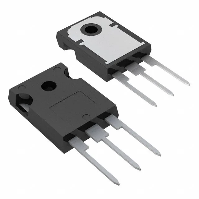
Each diode in the pair is rated for 20 A average rectified current, so the total package can handle 40 A in a common-cathode configuration — typical for a centre-tapped secondary or a dual-boost interleaved PFC. The TO-247-3 package has a large copper tab that bolts to a heatsink; the 15 µA reverse leakage at 600 V is low enough that it won't shift the thermal bias at high junction temperatures. For a 20 A continuous load, expect the tab temperature to settle around 100–120°C with forced air — the 175°C junction limit provides a comfortable derating margin.