800 V, 2 A ultrafast — what the ratings mean for the BOM
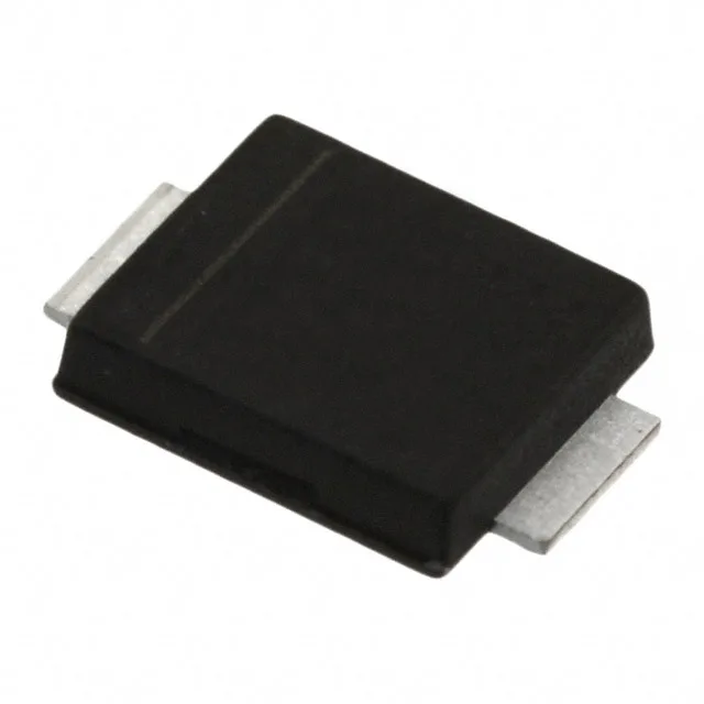
The STTH208UFY is an 800 V, 2 A ultrafast rectifier in the SMBflat (DO-221AA) surface-mount package, qualified to AEC-Q101 for automotive deployment. The 75 ns reverse recovery time places it in the 50-100 ns band typical for hard-switched boost PFC stages, secondary-side freewheeling diodes in DC-DC converters, and output rectification in on-board chargers or traction inverter auxiliary supplies. The 800 V blocking voltage provides a 2× margin above a 400 V nominal bus for load-dump transients in an EV traction system. The 2 A average current rating sets the continuous load ceiling — at full rated current and 25°C, the 1.55 V forward drop produces 3.1 W conduction loss, so the PCB copper pad area under the SMBflat cathode tab must be sized to keep the junction below the 175°C maximum. The 5 µA reverse leakage at 800 V and 25°C is low for an 800 V ultrafast, but leakage doubles roughly every 10°C — at 150°C junction the leakage current approaches the mA range, which matters for standby power budgets in always-on automotive modules.
Automotive-grade qualification and package reality
AEC-Q101 qualification (Grade 0 implied by the -40°C to 175°C junction range) means this diode has passed the automotive reliability stress suite: temperature cycling, high-temperature reverse bias (HTRB), high-humidity high-temperature reverse bias (H3TRB), and power cycling. It fits under-hood ECUs, engine-bay sensor power supplies, and cabin-domain DC-DC stages that see 105°C ambient with self-heating margin to 175°C junction. The SMBflat (DO-221AA) package is a low-profile surface-mount footprint with a flat lead frame — the solder joint is visible for automated optical inspection (AOI), and the 1.1 mm typical height suits tight PCB stack-ups in sealed electronic control units. The package is compatible with standard SMB pad layouts, but the flat leads require a different solder paste stencil aperture than gull-wing SMB parts; verify the footprint drawing before committing the PCB. The part is available through authorized distribution for current and future BOM lines.
Switching-speed context and peer comparison
The 75 ns trr at 2 A is a typical figure for an ultrafast diode in this voltage class — it keeps switching losses manageable at 100-200 kHz hard-switched frequencies, but the recovery softness (the di/dt at turn-off, or the Irrm/trr ratio) is not specified in the summary data. A buyer designing for conducted EMI compliance should verify the full recovery waveform from the ST datasheet or request characterization data from the distributor. The STTH310UFY (3 A, 1000 V, 75 ns trr, same SMBflat package and AEC-Q101 grade) is the higher-current, higher-voltage sibling. A BOM line that needs more margin on current or voltage could migrate up without a PCB change — the pad layout is identical. The STTH2R06UFY (2 A, 600 V, 85 ns trr, same package and grade) is the lower-voltage sibling; if the bus voltage never exceeds 600 V, this part may offer a lower forward voltage and cost savings.