50 ns reverse recovery — the switching-speed anchor
That 50 ns trr is the spec that separates this part from a standard recovery rectifier — it lets the diode turn off fast enough to keep switching losses low in a continuous-conduction-mode PFC stage or a 100–200 kHz LLC converter. The 2.95 V forward drop at 15 A is the trade-off: you get the speed, but the forward loss is higher than a slower ultrafast diode would show at the same current.
AEC-Q101 and 175°C junction — built for the engine bay
The 175°C ceiling is the standard for under-hood and EV traction applications where the heatsink sits in a 125°C ambient and the diode's own dissipation adds another 30–40°C. The 'Y' suffix in the order code flags the automotive flow — PPAP documentation, change-control notification, and lot traceability are in place for production releases.
TO-220AC package — the through-hole power tab
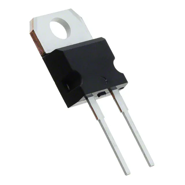
The diode comes in a TO-220AC (TO-220-2) through-hole package. The metal tab is the anode connection; the cathode is the center lead. For a 15 A average current, the tab needs a heatsink — the junction-to-case thermal path is the limiting factor, not the silicon itself. Through-hole mounting suits point-of-load rectifier stages on a main power board where the diode is hand-soldered or wave-soldered alongside the electrolytic capacitors and the PFC choke.
20 µA leakage at 600 V — the off-state check
Reverse leakage is specified at 20 µA at the full 600 V blocking voltage. That is a room-temperature typical; at 150°C junction the leakage will multiply, but the 175°C rating means the die is designed to handle it without thermal runaway. For a 400 V DC bus (typical PFC output), the margin is generous — the diode sees about 400 V in the off state, well below the 600 V rating.